Datasheet 搜索 > 陶瓷电容 > Vishay Semiconductor(威世) > A104K15X7RF5UAA 数据手册 > A104K15X7RF5UAA 数据手册 1/8 页

¥ 0.261
A104K15X7RF5UAA 数据手册 - Vishay Semiconductor(威世)
制造商:
Vishay Semiconductor(威世)
分类:
陶瓷电容
描述:
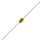
VISHAY A104K15X7RF5UAA 陶瓷电容, 0.1uF, 50V, X7R, 轴向引线
Pictures:
3D模型
符号图
焊盘图
引脚图
产品图
页面导航:
导航目录
A104K15X7RF5UAA数据手册
Page:
of 8 Go
若手册格式错乱,请下载阅览PDF原文件
A Series
www.vishay.com
Vishay BCcomponents
Revision: 20-Aug-13
1
Document Number: 45164
For technical questions, contact: cmll@vishay.com
THIS DOCUMENT IS SUBJECT TO CHANGE WITHOUT NOTICE. THE PRODUCTS DESCRIBED HEREIN AND THIS DOCUMENT
ARE SUBJECT TO SPECIFIC DISCLAIMERS, SET FORTH AT www.vishay.com/doc?91000
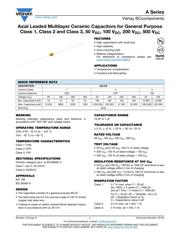
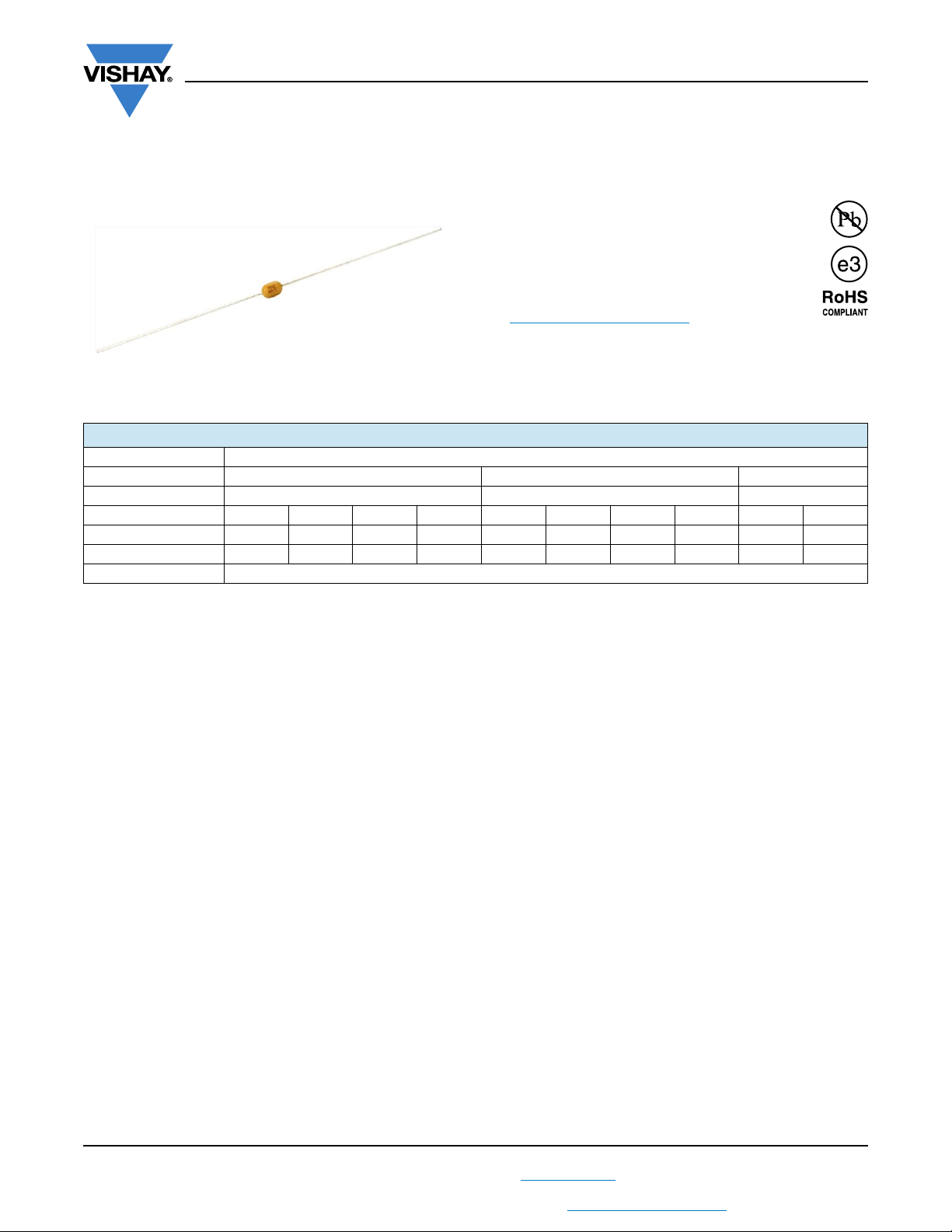
Axial Leaded Multilayer Ceramic Capacitors for General Purpose
Class 1, Class 2 and Class 3, 50 V
DC
, 100 V
DC
, 200 V
DC
, 500 V
DC
FEATURES
• High capacitance with small size
• High reliability
• Axial mounting style
• Material categorization:
For definitions of compliance please see
www.vishay.com/doc?99912
APPLICATIONS
• Temperature compensation
• Coupling and decoupling
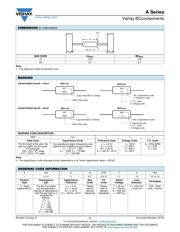
MARKING
Marking indicates capacitance value and tolerance in
accordance with “EIA 198” and voltage marks.
OPERATING TEMPERATURE RANGE
C0G, X7R: - 55 °C to + 125 °C
Y5V: - 30 °C to + 85 °C
TEMPERATURE CHARACTERISTICS
Class 1: C0G
Class 2: X7R
Class 3: Y5V
SECTIONAL SPECIFICATIONS
Climatic category (acc. to EN 60058-1)
Class 1 and 2: 55/125/21
Class 3: 30/85/21
APPROVALS
EIA 198
IEC 60384-9
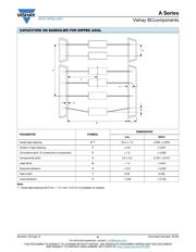
DESIGN
• The capacitors consist of a general purpose MLCC
• The lead wires are 0.5 mm and are made of 100 % tinned
copper clad steel wire
• Coating is made of yellow colored flame retardant epoxy
resin in accordance with UL 94 V-0
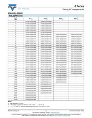
CAPACITANCE RANGE
10 pF to 1 μF
TOLERANCE ON CAPACITANCE
± 5 %, ± 10 %, ± 20 %, + 80 %/- 20 %
RATED VOLTAGE
50 V
DC
, 100 V
DC
, 200 V
DC
, 500 V
DC
TEST VOLTAGE
• 50 V
DC
and 100 V
DC
: 250 % of rated voltage
• 200 V
DC
: 150 % of rated voltage + 100 V
DC
• 500 V
DC
: 130 % of rated voltage + 100 V
DC
INSULATION RESISTANCE AT 500 V
DC
• 50 V
DC
and 100 V
DC
: 100 G or 1000 F whichever is less
at rated voltage within 2 min of charging
• 200 V
DC
and 500 V
DC
: 10 G or 100 F whichever is less
at rated voltage within 2 min of charging
DISSIPATION FACTOR
Class 1: 0.1 % max. when C 30 pF
(at 1 MHz; 1 V where C 1000 pF,
and at 1 kHz; 1 V where C > 1000 pF)
For C < 30 pF: DF = 100/(400 + 20 x C)
DF = Disspation factor in %;
C = Capacitance value in pF
Class 2: 2.5 % max. (at 1 kHz; 1 V)
Class 3: 5 % max. (at 1 kHz; 1 V)
QUICK REFERENCE DATA
DESCRIPTION VALUE
Ceramic Class 1 2 3
Ceramic Dielectric C0G X7R Y5V
Voltage (V
DC
) 50 100 200 500 50 100 200 500 50 100
Min. Capacitance (pF) 10 10 33 33 100 100 100 100 10 000 10 000
Max. Capacitance (pF) 10 000 5600 2200 1000 1 000 000 220 000 47 000 33 000 1 000 000 220 000
Mounting Axial
器件 Datasheet 文档搜索
AiEMA 数据库涵盖高达 72,405,303 个元件的数据手册,每天更新 5,000 多个 PDF 文件
