Datasheet 搜索 > 8位微控制器 > ATMEL(爱特美尔) > ATMEGA128A-AU 数据手册 > ATMEGA128A-AU 数据手册 122/386 页
 器件3D模型
¥ 15.026
ATMEGA128A-AU 数据手册 - ATMEL(爱特美尔)
制造商:
ATMEL(爱特美尔)
分类:
8位微控制器
封装:
TQFP-64
描述:
ATMEL ATMEGA128A-AU 微控制器, 8位, 低功率高性能, ATmega, 16 MHz, 128 KB, 4 KB, 64 引脚, TQFP
Pictures:
3D模型
符号图
焊盘图
引脚图
产品图
页面导航:
引脚图在P2P5P67P93P112P148Hot
原理图在P3P9P65P93P95P96P97P113P119P120P122P124
封装尺寸在P373P374
型号编码规则在P372P378
封装信息在P373
应用领域在P27P51P60P63P277P281P288P291P292
电气规格在P90P378
导航目录
ATMEGA128A-AU数据手册
Page:
of 386 Go
若手册格式错乱,请下载阅览PDF原文件
122
8151H–AVR–02/11
ATmega128A
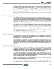
Register has been read. After a change of the edge, the Input Capture flag (ICFn) must be
cleared by software (writing a logical one to the I/O bit location). For measuring frequency only,
the clearing of the ICFn flag is not required (if an interrupt handler is used).
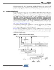
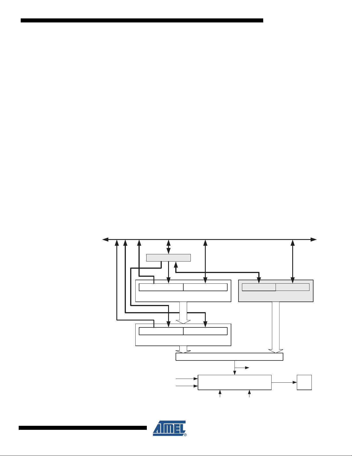
15.7 Output Compare Units
The 16-bit comparator continuously compares TCNTn with the Output Compare Register
(OCRnx). If TCNT equals OCRnx the comparator signals a match. A match will set the Output
Compare Flag (OCFnx) at the next timer clock cycle. If enabled (OCIEnx = 1), the output com-
pare flag generates an output compare interrupt. The OCFnx flag is automatically cleared when
the interrupt is executed. Alternatively the OCFnx flag can be cleared by software by writing a
logical one to its I/O bit location. The Waveform Generator uses the match signal to generate an
output according to operating mode set by the Waveform Generation mode (WGMn3:0) bits and
Compare Output mode (COMnx1:0) bits. The TOP and BOTTOM signals are used by the wave-
form generator for handling the special cases of the extreme values in some modes of operation
(See “Modes of Operation” on page 125.)
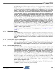
A special feature of output compare unit A allows it to define the Timer/Counter TOP value (that
is, counter resolution). In addition to the counter resolution, the TOP value defines the period
time for waveforms generated by the waveform generator.
Figure 15-4 shows a block diagram of the output compare unit. The small “n” in the register and
bit names indicates the device number (n = n
for Timer/Counter n), and the “x” indicates output
compare unit (A/B/C). The elements of the block diagram that are not directly a part of the output
compare unit are gray shaded.
Figure 15-4. Output Compare Unit, Block Diagram
OCFnx (Int.Req.)
=
(16-bit Comparator )
OCRnx Buffer (16-bit Register)
OCRnxH Buf. (8-bit)
OCnx
TEMP (8-bit)
DATA B US
(8-bit)
OCRnxL Buf. (8-bit)
TCNTn (16-bit Counter)
TCNTnH (8-bit) TCNTnL (8-bit)
COMnx1:0WGMn3:0
OCRnx (16-bit Register)
OCRnxH (8-bit) OCRnxL (8-bit)
Waveform Generator
TOP
BOTTOM
器件 Datasheet 文档搜索
AiEMA 数据库涵盖高达 72,405,303 个元件的数据手册,每天更新 5,000 多个 PDF 文件
