Datasheet 搜索 > 微控制器 > Microchip(微芯) > DSPIC30F2010-20E/SOG 数据手册 > DSPIC30F2010-20E/SOG 数据手册 67/202 页

 器件3D模型
¥ 34.963
DSPIC30F2010-20E/SOG 数据手册 - Microchip(微芯)
制造商:
Microchip(微芯)
分类:
微控制器
封装:
SOIC
Pictures:
3D模型
符号图
焊盘图
引脚图
产品图
页面导航:
引脚图在P5P95P192Hot
原理图在P8P15P53P58P62P63P67P71P75P82P92P96
标记信息在P185
封装信息在P148P185P190P192P201
功能描述在P91P95
技术参数、封装参数在P117P149P153P154P156P158P180P181P192
电气规格在P57P61P113P117P155P192
导航目录
DSPIC30F2010-20E/SOG数据手册
Page:
of 202 Go
若手册格式错乱,请下载阅览PDF原文件
© 2011 Microchip Technology Inc. DS70118J-page 67
dsPIC30F2010
11.0 INPUT CAPTURE MODULE
This section describes the Input Capture module and
associated operational modes. The features provided
by this module are useful in applications requiring Fre-
quency (Period) and Pulse measurement. Figure 11-1
depicts a block diagram of the Input Capture module.
Input capture is useful for such modes as:
• Frequency/Period/Pulse Measurements
• Additional sources of External Interrupts
The key operational features of the Input Capture
module are:
• Simple Capture Event mode
• Timer2 and Timer3 mode selection
• Interrupt on input capture event
These operating modes are determined by setting the
appropriate bits in the ICxCON register (where
x = 1,2,...,N). The dsPIC DSC devices contain up to
eight capture channels, (i.e., the maximum value of
N is 8).
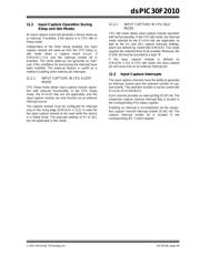
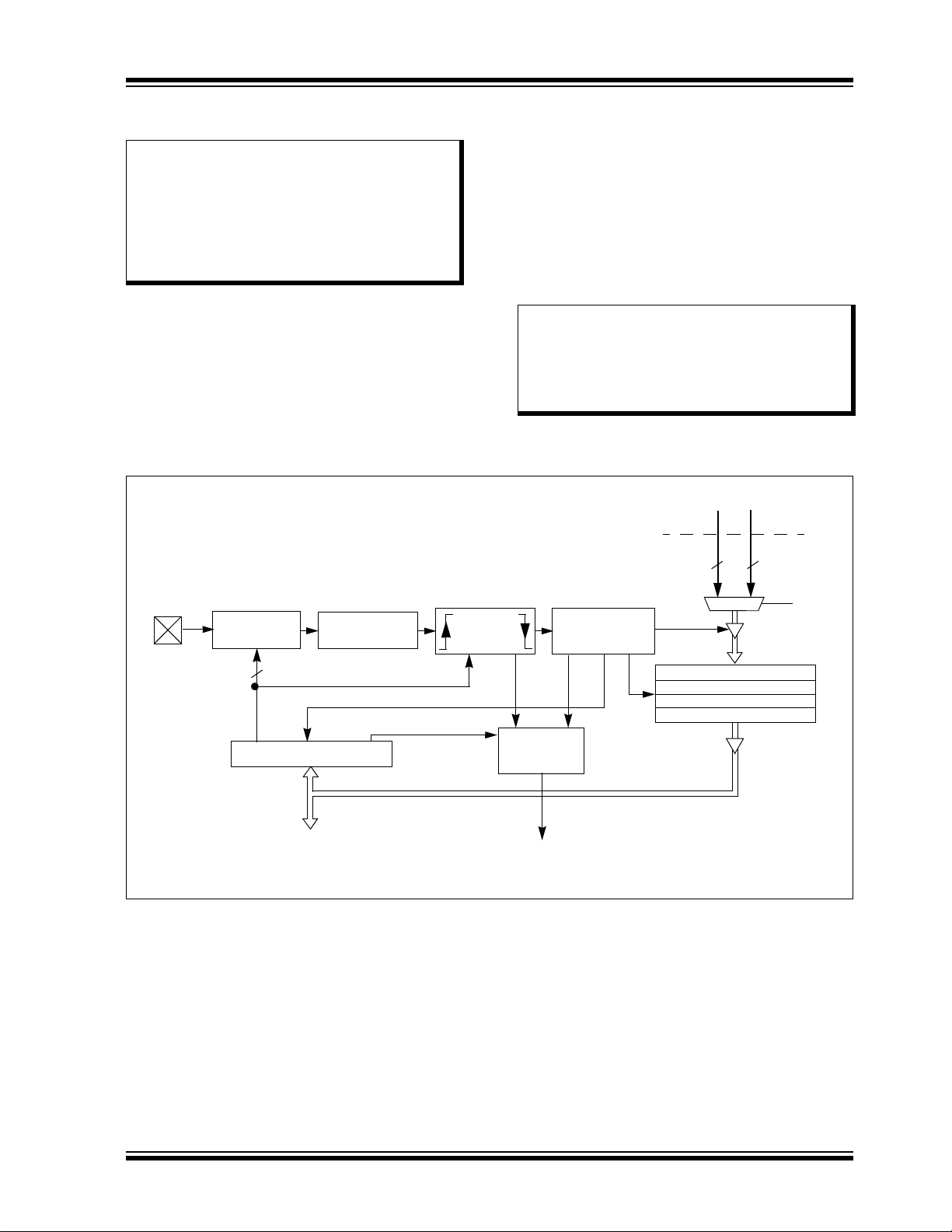
FIGURE 11-1: INPUT CAPTURE MODE BLOCK DIAGRAM
Note: This data sheet summarizes features of
this group of dsPIC30F devices and is not
intended to be a complete reference
source. For more information on the CPU,
peripherals, register descriptions and
general device functionality, refer to the
“dsPIC30F Family Reference Manual”
(DS70046).
Note: The dsPIC30F2010 device has four
capture inputs – IC1, IC2, IC7 and IC8.
The naming of these four capture chan-
nels is intentional and preserves software
compatibility with other dsPIC DSC
devices.
ICxBUF
Prescaler
ICx
ICM<2:0>
Mode Select
3
Note: Where ‘x’ is shown, reference is made to the registers or bits associated to the respective input capture channels 1 through N.
10
Set Flag
Pin
ICxIF
ICTMR
T2_CNT
T3_CNT
Edge
Detection
Logic
Clock
Synchronizer
1, 4, 16
From General Purpose Timer Module
16 16
FIFO
R/W
Logic
ICI<1:0>
ICBNE, ICOV
ICxCON
Interrupt
Logic
Set Flag
ICxIF
Data Bus
器件 Datasheet 文档搜索
AiEMA 数据库涵盖高达 72,405,303 个元件的数据手册,每天更新 5,000 多个 PDF 文件
