Datasheet 搜索 > Microchip(微芯) > JANTXV1N5811/TR 数据手册 > JANTXV1N5811/TR 数据手册 1/5 页

¥ 112.831
JANTXV1N5811/TR 数据手册 - Microchip(微芯)
制造商:
Microchip(微芯)
Pictures:
3D模型
符号图
焊盘图
引脚图
产品图
页面导航:


导航目录
JANTXV1N5811/TR数据手册
Page:
of 5 Go
若手册格式错乱,请下载阅览PDF原文件
T4-LDS-0168, Rev. 3 (120776) ©2012 Microsemi Corporation Page 1 of 5
1N5807, 1N5809 and 1N5811
Available on
commercial
versions
VOID-LESS HERMETICALLY SEALED ULTRAFAST
RECOVERY GLASS RECTIFIERS
Qualified per MIL-PRF-19500/477
Qualified Levels:
JAN, JANTX,
JANTXV and JANS
DESCRIPTION
This “Ultrafast Recovery” rectifier diode series is military qualified and is ideal for high-reliability
applications where a failure cannot be tolerated. The industry-recognized 6.0 amp rated rectifiers
with working peak reverse voltages from 50 to 150 volts are hermetically sealed with void-less glass
construction using an internal “Category 1” metallurgical bond. These devices are available in both
leaded and surface mount MELF package configurations. Microsemi also offers numerous other
rectifier products to meet higher and lower current ratings with various recovery time requirements
including standard, fast and ultrafast device types in both through-hole and surface mount
packages.
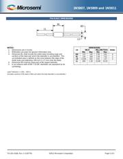
“B” Package
Also available in:
“B” MELF Package
(surface mount)
1N5807, 09, 11US & URS
Important: For the latest information, visit our website http://www.microsemi.com.
FEATURES
• JEDEC registered 1N5807, 1N5809, 1N5811 series.
• Void-less hermetically sealed glass package.
• Quadruple-layer passivation.
• Extremely robust construction.
• Internal “Category 1” metallurgical bonds.
• JAN, JANTX, JANTXV and JANS qualifications are availble per MIL-PRF-19500/477.
• RoHS compliant versions available (commercial grade only).
APPLICATIONS / BENEFITS
• Ultrafast recovery 6 amp rectifier series from 50 to 150 V.
• Military, space and other high-reliability applications.
• Switching power supplies or other applications requiring extremely fast switching & low forward
loss.
• High forward surge current capability.
• Low thermal resistance.
• Controlled avalanche with peak reverse power capability.
• Inherently radiation hard as described in Microsemi MicroNote 050.
MAXIMUM RATINGS @ T
A
= 25
o
C unless otherwise specified
MSC – Lawrence
6 Lake Street,
Lawrence, MA 01841
Tel: 1-800-446-1158 or
(978) 620-2600
Fax: (978) 689-0803
MSC – Ireland
Gort Road Business Park,
Ennis, Co. Clare, Ireland
Tel: +353 (0) 65 6840044
Fax: +353 (0) 65 6822298
Website:
www.microsemi.com
Parameters/Test Conditions
Symbol
Value
Unit
Junction and Storage Temperature
T
J
and T
STG
-65 to +175
o
C
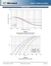
Thermal Resistance Junction-to-Lead (L = .375 in) Fig. 1
R
ӨJL
22
o
C/W
Thermal Resistance
R
ӨJX
52
o
C/W
Working Peak Reverse Voltage:
1N5807
1N5809
1N5811
V
RWM
50
100
150
V
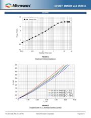
Forward Surge Current
(3)
I
FSM
125
A
Average Rectified Output Current
@ T
L
= +75
o
C at 3/8 inch lead length
(1)
I
O1
6.0 A
Average Rectified Output-Current
@ T
A
= +55
o
C at 3/8 inch lead length
(2)
I
O2
3.0 A
Capacitance @ V
R
= 10 V, f = 1 MHz; Vsig = 50 mV (p-p)
C
J
60
pF
Reverse Recovery Time
(4)
t
rr
30
ns
Solder Temperature @ 10 s
T
SP
260
o
C
Notes: 1. I
O1
is rated at T
L
= 75
o
C at 3/8 inch lead length. Derate at 60 mA/
o
C for T
L
above 75
o
C.
2. I
O2
is derated at 25 mA/ºC above T
A
= 55
o
C for PC boards where thermal resistance from mounting
point to ambient is sufficiently controlled where T
J(max)
175
o
C is not exceeded.
3. T
A
= 25
o
C @ I
O
= 3.0 A and V
RWM
for ten 8.3 ms surges at 1 minute intervals.
4. I
F
= 1.0 A, I
RM
= 1.0 A, I
R(REC)
= .0.10 A and di/dt = 100 A/µs min.
器件 Datasheet 文档搜索
AiEMA 数据库涵盖高达 72,405,303 个元件的数据手册,每天更新 5,000 多个 PDF 文件
