Datasheet 搜索 > 稳压芯片 > TI(德州仪器) > LM317MDCYRG3 数据手册 > LM317MDCYRG3 数据手册 10/22 页

¥ 0.98
LM317MDCYRG3 数据手册 - TI(德州仪器)
制造商:
TI(德州仪器)
分类:
稳压芯片
封装:
TO-261-4
描述:
TEXAS INSTRUMENTS LM317MDCYRG3 芯片, 可调线性稳压器 1.25V 至 37V SOT-223-4, 整卷
Pictures:
3D模型
符号图
焊盘图
引脚图
产品图
页面导航:
导航目录
LM317MDCYRG3数据手册
Page:
of 22 Go
若手册格式错乱,请下载阅览PDF原文件
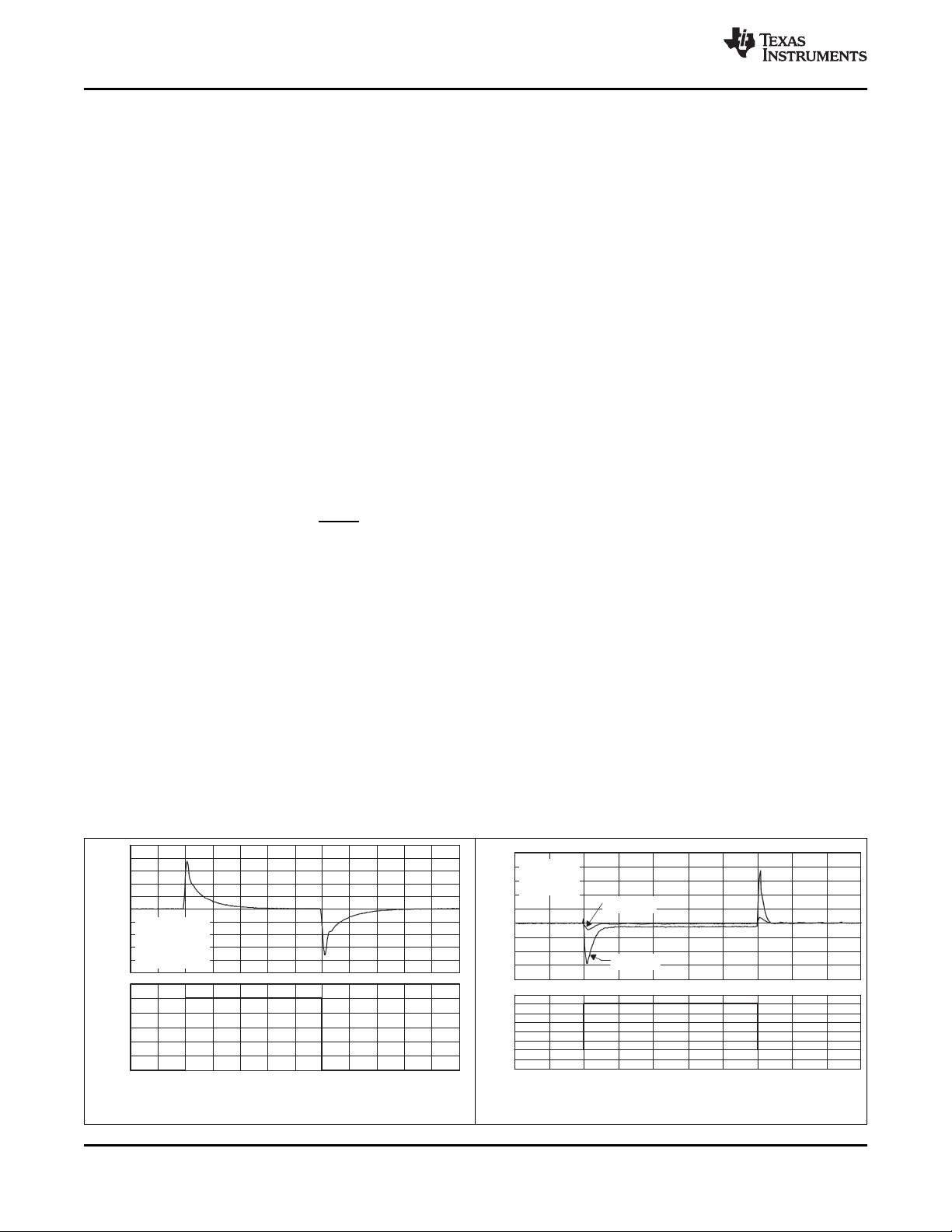
−10
Time − µs
−0.2
∆I
O
− Output Current Change − A
∆V
O
− Output Voltage Change − V
−5 0 5 10 15 20 25 30 35
−0.1
0
0.1
0.2
0.3
0.4
0.5
0.6
−4.0
−3.0
−2.0
−1.0
0
1.0
2.0
3.0
4.0
5.0
V
I
= 15 V
V
O
= 10 V
I
L
= 50 mA
∆I
L
= +500 mA
C
L
= 1 µF
C
ADJ
= 10 µF
C
L
= 0 µF
C
ADJ
= 0 µF
−1.0
Time − µs
−0.5 0 0.5 1.0 1.5 2.0 2.5 3.0 3.5 4.0 4.5
1.2
1
0.8
0.6
0.4
0.2
0
−1
−0.8
−0.6
−0.4
−0.2
0
0.2
0.4
0.6
0.8
1
V
O
= 10 V
V
I
= 15 V, ∆V
I
= +1 V
I
L
= 50 mA
T
J
= 25°C
C
L
= 0 µF
C
ADJ
= 0 µF
∆V
I
− Input Voltage Change − V
∆V
O
− Output Voltage Change − V
)()1(
2
1
2
RI
R
R
VV
adjrefo
uu
LM317M
SLVS297P –APRIL 2000–REVISED MARCH 2014
www.ti.com
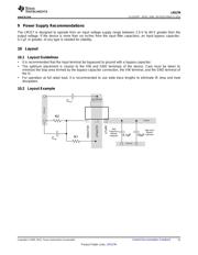
8.2.2.5 Protection Diodes
If the input is shorted to ground during a fault condition, protection diode (D1) prevents discharge through the
LM317M. If the output is shorted to ground during a fault condition, protection diode (D2) prevents adjust terminal
capacitor discharge through the LM317M.
8.2.2.6 Design Options and Parameters
Common Linear Regulator designs are concerned with the following parameters:
• Input voltage range
• Input Capacitor range
• Output voltage
• Output current rating
• Output capacitor range
• Input Short Protection
• Stability
• Ripple Rejection
8.2.2.7 Output Voltage
Vo is calculated as shown:
(3)
Because I
adj
typically is 50-µA, it is negligible in most applications.
8.2.2.8 Ripple Rejection
C
ADJ
is used to improve ripple rejection; it prevents amplification of the ripple as the output voltage is adjusted
higher. If C
ADJ
is used, it is best to include protection diodes.
8.2.2.9 Input Short Protection
If the input is shorted to ground during a fault condition, protection diodes provide measures to prevent the
possibility of external capacitors discharging through low-impedance paths in the IC. By providing low-impedance
discharge paths for C
O
and C
ADJ
, respectively, D1 and D2 prevent the capacitors from discharging into the output
of the regulator.
8.2.3 Application Curves
Figure 12. Line Transient Response vs Time
Figure 13. Load Transient Response vs Time
10 Submit Documentation Feedback Copyright © 2000–2014, Texas Instruments Incorporated
Product Folder Links: LM317M
器件 Datasheet 文档搜索
AiEMA 数据库涵盖高达 72,405,303 个元件的数据手册,每天更新 5,000 多个 PDF 文件
