Datasheet 搜索 > Linear Technology(凌力尔特) > LTC4364HMS-2#TRPBF 数据手册 > LTC4364HMS-2#TRPBF 数据手册 13/24 页
 器件3D模型
¥ 46.372
LTC4364HMS-2#TRPBF 数据手册 - Linear Technology(凌力尔特)
制造商:
Linear Technology(凌力尔特)
封装:
MSOP-16
Pictures:
3D模型
符号图
焊盘图
引脚图
产品图
页面导航:
引脚图在P7P8Hot
典型应用电路图在P1P19P20P21P24
原理图在P9
封装尺寸在P21
焊盘布局在P22P23
型号编码规则在P3
标记信息在P3
封装信息在P3
技术参数、封装参数在P4
应用领域在P1P7P8P11P12P13P14P15P16P17P18P19
电气规格在P3P4P5P6P12
导航目录
LTC4364HMS-2#TRPBF数据手册
Page:
of 24 Go
若手册格式错乱,请下载阅览PDF原文件
LTC4364-1/LTC4364-2
13
436412f
I
TMR
= 5µA I
TMR
= 5µA
0
0
1.25
1.35
1.25
TIME
TIME
436412 F03
t
WARNING
20ms/µF
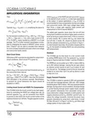
(3a) Overvoltage Fault Timer Current
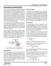
(3b) Overcurrent Fault Timer Current
t
WARNING
0.38ms/µF
t
WARNING
20ms/µF
t
F LT
25ms/µF
t
F LT
4.8ms/µF
t
WARNING
2.38ms/µF
t
F LT
29.8ms/µF
t
F LT
156ms/µF
1.35
V
TMR
(V)
V
TMR
(V)
V
CC
– V
OUT
= 75V
(I
TMR
= 50µA)
V
CC
– V
OUT
= 75V
=10V
V
CC
– V
OUT
= 75V
=10V
V
CC
– V
OUT
= 75V
(I
TMR
= 260µA)
V
CC
– V
OUT
= 10V
(I
TMR
= 42µA)
V
CC
– V
OUT
= 10V
(I
TMR
= 8µA)
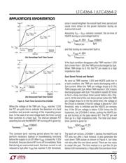
Figure 3. Fault Timer Current of the LTC4364
When the voltage at the TMR pin, V
TMR
, reaches 1.25V,
the F LT pin pulls low to indicate the detection of a fault
condition and provide warning of the impending power
loss. In the case of an overvoltage fault, the timer current
then switches to a fixed 5μA. The interval between F LT
asserting low and the MOSFET M1 turning off is given by:
t
WARNING
=
C
TMR
• 100mV
5µA
This constant early warning period allows the load to
perform necessary backup or housekeeping functions
before the supply is cut off. After V
TMR
crosses the 1.35V
threshold, the pass device M1 turns off immediately. Note
that during an overcurrent event, the timer current is not
reduced to 5μA after V
TMR
has reached 1.25V threshold,
since it would lengthen the overall fault timer period and
cause more stress on the power transistor during an
overcurrent event.
Assuming V
CC
– V
OUT
remains constant, the on-time of
HGATE during an overvoltage fault is:
t
OV
=
C
TMR
• 1.25V
I
TMR(UP)OV
+
C
TMR
• 100mV
5µV
and that during an overcurrent fault is:
t
OC
=
C
TMR
• 1.35V
I
TRM(UP)OC
If the fault condition disappears after TMR reaches 1.25V
but is lower than 1.35V, the TMR pin is discharged by 2μA.
When TMR drops to 0.15V, the F LT pin resets to a high
impedance state.
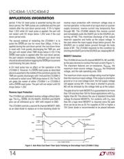
Cool Down Period and Restart
As soon as TMR reaches 1.35V and HGATE pulls low in
a fault condition, the TMR pin starts discharging with a
2μA current. When the TMR pin voltage drops to 0.15V,
TMR charges with 2μA. When TMR reaches 1.35V, it starts
discharging again with 2μA. This pattern repeats 32 times
to form a long cool down timer period before retry (Fig-
ure4). At the end of the cool down period (when the TMR
pin voltage drops to 0.15V the 32nd time), the voltage at
the OV pin is checked. If the OV voltage is above its 1.25V
threshold, retry is inhibited and the HGATE pin remains
low. If the OV pin voltage is below 1.25V minus the OV
hysteresis, the LTC4364-2 retries, pulling the HGATE pin
up and turning on the pass device M1. The F LT pin will
then go to a high impedance state. The total cool down
timer period is given by:
t
COOL
=
63 • C
TMR
• 1.2V
2µA
The latch-off version, LTC4364-1, latches the HGATE and
F LT pins low after a fault timeout. It also generates the
cool down TMR pulses as shown in Figure 4, but does
not retry after the cool down period. There are two ways
to restart the part. The first method is to pull the UV pin
below 0.6V momentarily (>10μs) after the cool down timer
APPLICATIONS INFORMATION
器件 Datasheet 文档搜索
AiEMA 数据库涵盖高达 72,405,303 个元件的数据手册,每天更新 5,000 多个 PDF 文件
