Datasheet 搜索 > 放大器、缓冲器 > Microchip(微芯) > MCP6S26-I/SL 数据手册 > MCP6S26-I/SL 数据手册 3/42 页
 器件3D模型
¥ 0.361
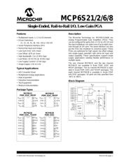
MCP6S26-I/SL 数据手册 - Microchip(微芯)
制造商:
Microchip(微芯)
分类:
放大器、缓冲器
封装:
SOIC-14
描述:
MICROCHIP MCP6S26-I/SL 可编程/可变增益放大器, 6 放大器, 1个放大器, 12 MHz, -40 °C, 125 °C, 2.5V 至 5.5V
Pictures:
3D模型
符号图
焊盘图
引脚图
产品图
页面导航:
引脚图在P15Hot
典型应用电路图在P1P26
原理图在P1P16
标记信息在P28P29P30
封装信息在P28P31P32P33P34P35P36P37P38P39
技术参数、封装参数在P3P4P5P22
应用领域在P1P17P25P26
电气规格在P3P4P5P22P25
导航目录
MCP6S26-I/SL数据手册
Page:
of 42 Go
若手册格式错乱,请下载阅览PDF原文件
2003-2012 Microchip Technology Inc. DS21117B-page 3
MCP6S21/2/6/8
Power Supply
Supply Voltage V
DD
2.5 — 5.5 V
Quiescent Current I
Q
0.5 1.0 1.35 mA I
O
= 0 (Note 2)
Quiescent Current, Shutdown
mode
I
Q_SHDN
—0.51.0 µAI
O
= 0 (Note 2)
Power-On Reset
POR Trip Voltage V
POR
1.2 1.7 2.2 V (Note 3)
POR Trip Voltage Drift V
POR
/T— -3.0 — mV/°CT
A
= -40°C to+85°C
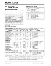
DC CHARACTERISTICS (CONTINUED)
Electrical Specifications: Unless otherwise indicated, T
A
= +25°C, V
DD
= +2.5V to +5.5V, V
SS
= GND, V
REF
= V
SS
, G = +1 V/V,
Input = CH0 = (0.3V)/G, CH1 to CH7 = 0.3V, R
L
=10kto V
DD
/2, SI and SCK are tied low and CS is tied high.
Parameters Sym Min Typ Max Units Conditions
Note 1: R
LAD
(R
F
+ R
G
in Figure 4-1) connects V
REF
, V
OUT
and the inverting input of the internal amplifier. The MCP6S22 has
V
REF
tied internally to V
SS
, so V
SS
is coupled to the internal amplifier and the PSRR spec describes PSRR+ only. We
recommend the MCP6S22’s V
SS
pin be tied directly to ground to avoid noise problems.
2: I
Q
includes current in R
LAD
(typically 60 µA at V
OUT
= 0.3V). Both I
Q
and I
Q_SHDN
exclude digital switching currents.
3: The output goes Hi-Z and the registers reset to their defaults; see Section 5.4, “Power-On Reset”.
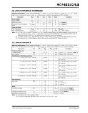
AC CHARACTERISTICS
Electrical Specifications: Unless otherwise indicated, T
A
= +25°C, V
DD
= +2.5V to +5.5V, V
SS
= GND, V
REF
= V
SS
, G = +1 V/V,
Input = CH0 =(0.3V)/G, CH1 to CH7=0.3V, R
L
=10kto V
DD
/2, C
L
= 60 pF, SI and SCK are tied low, and CS is tied high.
Parameters Sym Min Typ Max Units Conditions
Frequency Response
-3 dB Bandwidth BW — 2 to 12 — MHz All gains; V
OUT
< 100 mV
P-P
(Note 1)
Gain Peaking GPK — 0 — dB All gains; V
OUT
< 100 mV
P-P
Total Harmonic Distortion plus Noise
f = 1 kHz, G = +1 V/V THD+N — 0.0015 — %
V
OUT
= 1.5V ± 1.0V
PK
, V
DD
= 5.0V,
BW = 22 kHz
f = 1 kHz, G = +4 V/V THD+N — 0.0058 — %
V
OUT
= 1.5V ± 1.0V
PK
, V
DD
= 5.0V,
BW = 22 kHz
f = 1 kHz, G = +16 V/V THD+N — 0.023 — %
V
OUT
= 1.5V ± 1.0V
PK
, V
DD
= 5.0V,
BW = 22 kHz
f = 20 kHz, G = +1 V/V THD+N — 0.0035 — %
V
OUT
= 1.5V ± 1.0V
PK
, V
DD
= 5.0V,
BW = 80 kHz
f = 20 kHz, G = +4 V/V THD+N — 0.0093 — %
V
OUT
= 1.5V ± 1.0V
PK
, V
DD
= 5.0V,
BW = 80 kHz
f = 20 kHz, G = +16 V/V THD+N — 0.036 — %
V
OUT
= 1.5V ± 1.0V
PK
, V
DD
= 5.0V,
BW = 80 kHz
Step Response
Slew Rate SR — 4.0 — V/µs G = 1, 2
— 11 — V/µs G = 4, 5, 8, 10
— 22 — V/µs G = 16, 32
Noise
Input Noise Voltage E
ni
—3.2—µV
P-P
f = 0.1 Hz to 10 kHz (Note 2)
— 26 — f = 0.1 Hz to 200 kHz (Note 2)
Input Noise Voltage Density e
ni
—10—nV/Hz f = 10 kHz (Note 2)
Input Noise Current Density i
ni
—4—fA/Hz f = 10 kHz
Note 1: See Table 4-1 for a list of typical numbers.
2: E
ni
and e
ni
include ladder resistance noise. See Figure 2-33 for e
ni
vs. G data.
器件 Datasheet 文档搜索
AiEMA 数据库涵盖高达 72,405,303 个元件的数据手册,每天更新 5,000 多个 PDF 文件
