Datasheet 搜索 > SCR晶闸管 > ON Semiconductor(安森美) > MCR12MG 数据手册 > MCR12MG 数据手册 1/4 页

¥ 2.353
MCR12MG 数据手册 - ON Semiconductor(安森美)
制造商:
ON Semiconductor(安森美)
分类:
SCR晶闸管
封装:
TO-220-3
描述:
ON SEMICONDUCTOR MCR12MG 晶闸管, SCR, 12A, 600V, TO-220AB, 12A, 600V
Pictures:
3D模型
符号图
焊盘图
引脚图
产品图
页面导航:
导航目录
MCR12MG数据手册
Page:
of 4 Go
若手册格式错乱,请下载阅览PDF原文件
© Semiconductor Components Industries, LLC, 2015
January, 2015 − Rev. 6
1 Publication Order Number:
MCR12/D
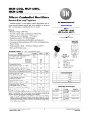
MCR12DG, MCR12MG,
MCR12NG
Silicon Controlled Rectifiers
Reverse Blocking Thyristors
Designed primarily for half-wave ac control applications, such as
motor controls, heating controls, and power supplies; or wherever
half−wave silicon gate−controlled devices are needed.
Features
• Blocking Voltage to 800 Volts
• On−State Current Rating of 12 Amperes RMS at 80°C
• High Surge Current Capability − 100 Amperes
• Rugged, Economical TO−220AB Package
• Glass Passivated Junctions for Reliability and Uniformity
• Minimum and Maximum Values of IGT, VGT an IH Specified for
Ease of Design
• High Immunity to dv/dt − 100 V/msec Minimum at 125°C
• These are Pb−Free Devices
MAXIMUM RATINGS (T
J
= 25°C unless otherwise noted)
Rating Symbol Value Unit
Peak Repetitive Off−State Voltage (Note 1
)
(T
J
= −40 to 125°C, Sine Wave,
50 to 60 Hz,
Gate Open)
MCR12DG
MCR12MG
MCR12NG
V
DRM,
V
RRM
400
600
800
V
On-State RMS Current
(180° Conduction Angles; T
C
= 80°C)
I
T(RMS)
12 A
Peak Non-repetitive Surge Current
(1/2 Cycle, Sine Wave 60 Hz, T
J
= 125°C)
I
TSM
100 A
Circuit Fusing Consideration (t = 8.33 ms) I
2
t 41 A
2
sec
Forward Peak Gate Power
(Pulse Width ≤ 1.0 ms, T
C
= 80°C)
P
GM
5.0 W
Forward Average Gate Power
(t = 8.3 ms, T
C
= 80°C)
P
G(AV)
0.5 W
Average On-State Current
(180° Conduction Angles; T
C
= 80°C)
I
T(AV)
7.8 A
Forward Peak Gate Current
(Pulse Width ≤ 1.0 ms, T
C
= 90°C)
I
GM
2.0 A
Operating Junction Temperature Range T
J
−40 to +125 °C
Storage Temperature Range T
stg
−40 to +150 °C
Stresses exceeding those listed in the Maximum Ratings table may damage the
device. If any of these limits are exceeded, device functionality should not be
assumed, damage may occur and reliability may be affected.
1. V
DRM
and V
RRM
for all types can be applied on a continuous basis. Ratings
apply for zero or negative gate voltage; positive gate voltage shall not be
applied concurrent with negative potential on the anode. Blocking voltages
shall not be tested with a constant current source such that the voltage ratings
of the devices are exceeded.
SCRs
12 AMPERES RMS
400 thru 800 VOLTS
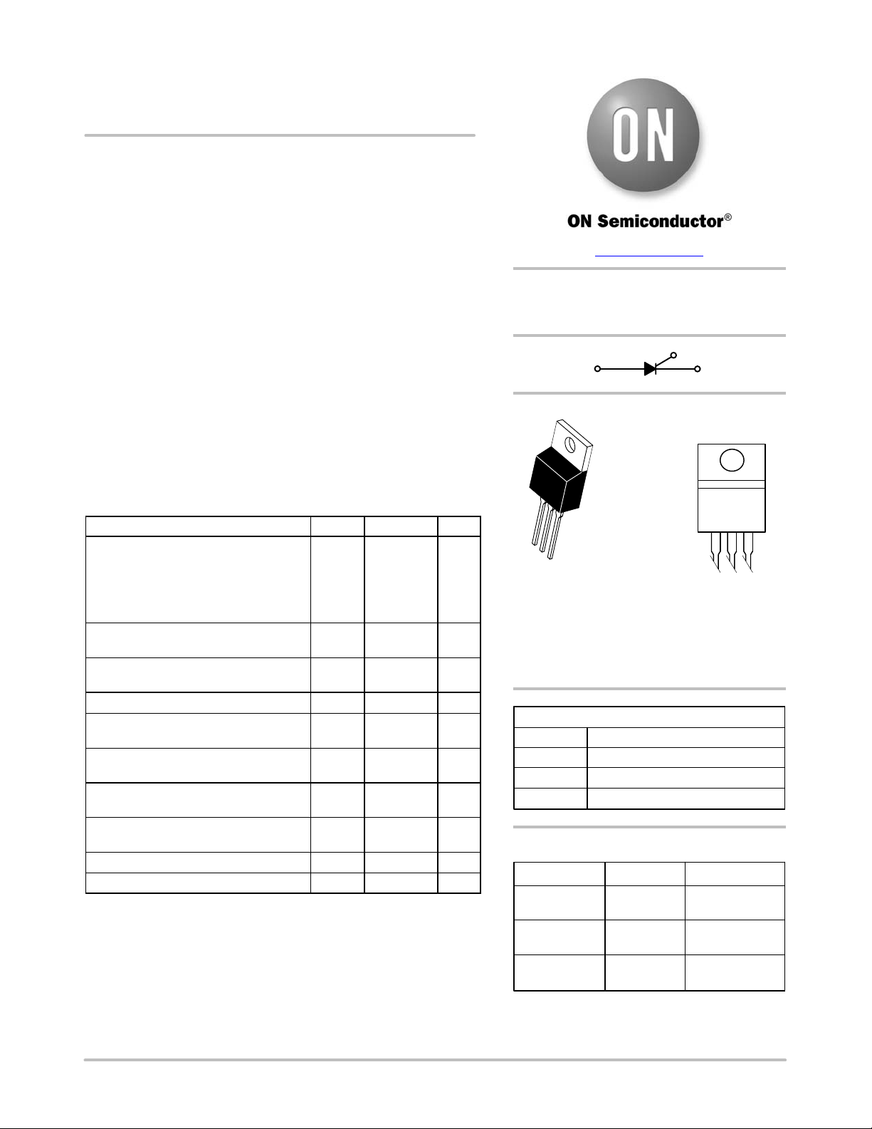
TO−220
CASE 221A−09
STYLE 3
1
www.onsemi.com
MARKING
DIAGRAM
A = Assembly Location
Y = Year
WW = Work Week
x = D, M, or N
G = Pb−Free Package
AKA = Diode Polarity
2
3
Device Package Shipping
ORDERING INFORMATION
MCR12DG TO−220AB
(Pb−Free)
50 Units / Rail
MCR12NG TO−220AB
(Pb−Free)
50 Units / Rail
MCR12MG TO−220AB
(Pb−Free)
50 Units / Rail
K
G
A
PIN ASSIGNMENT
1
2
3
Anode
Gate
Cathode
4
Anode
AY WW
MCR12xG
AKA
器件 Datasheet 文档搜索
AiEMA 数据库涵盖高达 72,405,303 个元件的数据手册,每天更新 5,000 多个 PDF 文件
