Datasheet 搜索 > 接口芯片 > TI(德州仪器) > PCF8574APWRG4 数据手册 > PCF8574APWRG4 数据手册 15/35 页
 器件3D模型
¥ 7.933
PCF8574APWRG4 数据手册 - TI(德州仪器)
制造商:
TI(德州仪器)
分类:
接口芯片
封装:
TSSOP-20
描述:
远程8位I / O扩展器I2C总线 REMOTE 8-BIT I/O EXPANDER FOR I2C BUS
Pictures:
3D模型
符号图
焊盘图
引脚图
产品图
页面导航:
引脚图在P3Hot
典型应用电路图在P15P16P17
原理图在P11P12P15
封装尺寸在P22P23P24P25
标记信息在P22P23
封装信息在P21P22P23P24P25
技术参数、封装参数在P4
应用领域在P1P35
电气规格在P5
导航目录
PCF8574APWRG4数据手册
Page:
of 35 Go
若手册格式错乱,请下载阅览PDF原文件
A1
A0
SDA
SCL
INT
GND
P6
P0
P1
P2
P3
P4
P5
P7
INT
GND
VCC
V
CC
V
CC
10 k
(1)
Ω 10 k
(1)
Ω
10 kΩ
2 kΩ
100 kΩ
(x
3)
Master
Controller
PCF8574A
INT
RESET
Subsystem 2
(e.g., counter)
Subsystem 3
(e.g., alarm system)
ALARM
Controlled Device
(e.g., CBT device)
ENABLE
A
B
V
CC
Subsystem 1
(e.g., temperature sensor)
SDA
SCL
15
14
16
13
3
2
1
8
12
11
10
9
7
6
5
4
A2
PCF8574A
www.ti.com
SCPS069F –JULY 2001–REVISED NOVEMBER 2015
9 Application and Implementation
NOTE
Information in the following applications sections is not part of the TI component
specification, and TI does not warrant its accuracy or completeness. TI’s customers are
responsible for determining suitability of components for their purposes. Customers should
validate and test their design implementation to confirm system functionality.
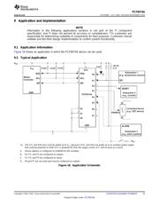
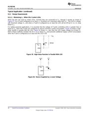
9.1 Application Information
Figure 18 shows an application in which the PCF8574A device can be used.
9.2 Typical Application
(1) The SCL and SDA pins must be pulled up to V
CC
because if SCL and SDA are pulled up to an auxiliary power supply
that could be powered on while VCC is powered off, then the supply current, ICC, will increase as a result.
A. Device address is configured as 0100000 for this example.
B. P0, P2, and P3 are configured as outputs.
C. P1, P4, and P5 are configured as inputs.
D. P6 and P7 are not used and must be configured as outputs.
Figure 18. Application Schematic
Copyright © 2001–2015, Texas Instruments Incorporated Submit Documentation Feedback 15
Product Folder Links: PCF8574A
器件 Datasheet 文档搜索
AiEMA 数据库涵盖高达 72,405,303 个元件的数据手册,每天更新 5,000 多个 PDF 文件
