Datasheet 搜索 > 微控制器 > Microchip(微芯) > PIC16C745-I/SO 数据手册 > PIC16C745-I/SO 数据手册 43/166 页
 器件3D模型
¥ 31.942
PIC16C745-I/SO 数据手册 - Microchip(微芯)
制造商:
Microchip(微芯)
分类:
微控制器
封装:
SOIC-28
描述:
MICROCHIP PIC16C745-I/SO 微控制器, 8位, 一次性可编程, PIC16C7xx, 24 MHz, 14 KB, 256 Byte, 28 引脚, SOIC
Pictures:
3D模型
符号图
焊盘图
引脚图
产品图
页面导航:
引脚图在P1P11P12P53P54Hot
原理图在P10P31P33P35P37P38P40P43P46P49P53P54
标记信息在P147P148
封装信息在P73P147P149P150P151P152P153P154P155
功能描述在P2P5
技术参数、封装参数在P103P112P132P133P143
应用领域在P58P66
电气规格在P103
导航目录
PIC16C745-I/SO数据手册
Page:
of 166 Go
若手册格式错乱,请下载阅览PDF原文件
1999-2013 Microchip Technology Inc. Preliminary DS41124D-page 43
PIC16C745/765
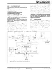
6.0 TIMER0 MODULE
The Timer0 module timer/counter has the following fea-
tures:
• 8-bit timer/counter
• Readable and writable
• 8-bit software programmable prescaler
• Internal or external clock select
• Interrupt-on-overflow from FFh to 00h
• Edge select for external clock
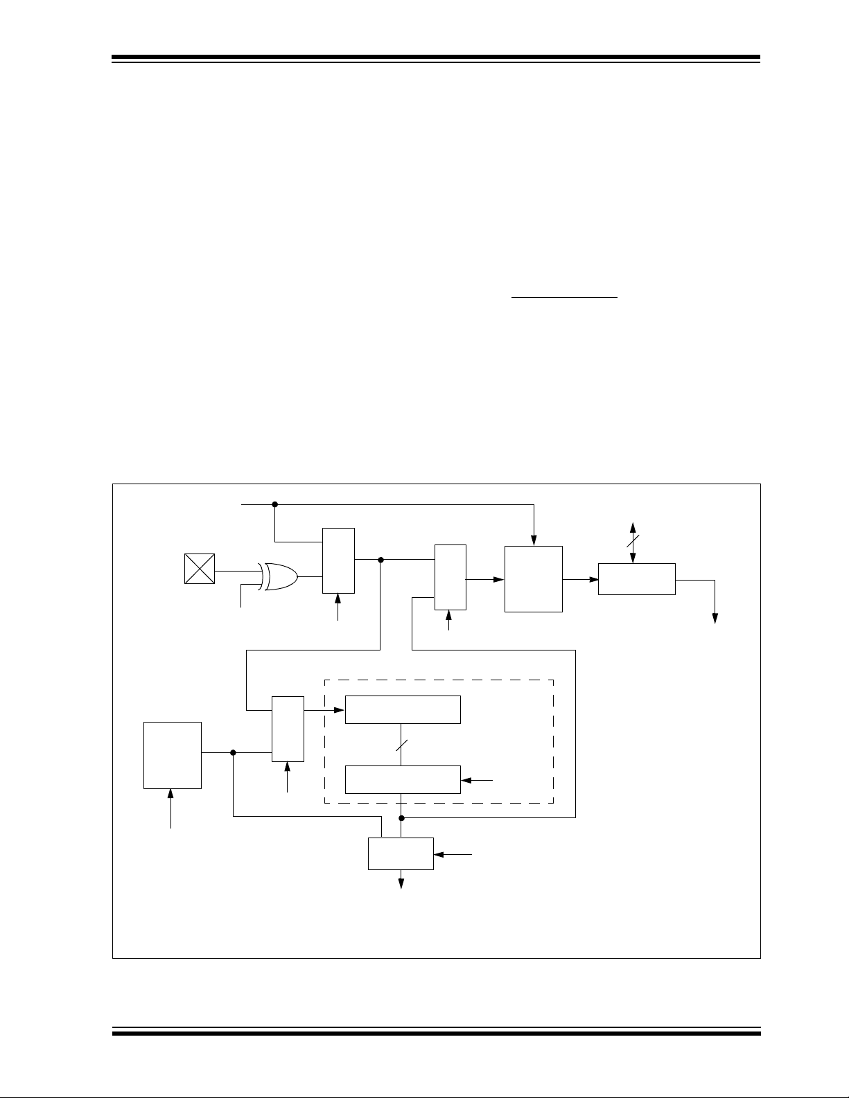
Figure 6-1 is a block diagram of the Timer0 module and
the prescaler shared with the WDT.
Additional information on the Timer0 module is avail-
able in the PIC Mid-Range MCU Family Reference
Manual (DS33023).
Timer mode is selected by clearing bit T0CS
(OPTION_REG<5>). In timer mode, the Timer0 mod-
ule will increment every instruction cycle (without pres-
caler). If the TMR0 register is written, the increment is
inhibited for the following two instruction cycles. The
user can work around this by writing an adjusted value
to the TMR0 register.
Counter mode is selected by setting bit T0CS
(OPTION_REG<5>). In counter mode, Timer0 will
increment either on every rising or falling edge of pin
RA4/T0CKI. The incrementing edge is determined by
the Timer0 Source Edge Select bit T0SE
(OPTION_REG<4>). Clearing bit T0SE selects the ris-
ing edge. Restrictions on the external clock input are
discussed in detail in Section 6.2.
The prescaler is mutually exclusively shared between
the Timer0 module and the watchdog timer. The pres-
caler is not readable or writable. Section 6.3 details the
operation of the prescaler.
6.1 Timer0 Interrupt
The TMR0 interrupt is generated when the TMR0 reg-
ister overflows from FFh to 00h. This overflow sets bit
T0IF (INTCON<2>). The interrupt can be masked by
clearing bit T0IE (INTCON<5>). Bit T0IF must be
cleared in software by the Timer0 module interrupt ser-
vice routine before re-enabling this interrupt. The
TMR0 interrupt cannot awaken the processor from
SLEEP, since the timer is shut off during SLEEP.
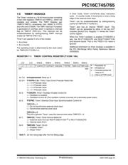
FIGURE 6-1: BLOCK DIAGRAM OF THE TIMER0/WDT PRESCALER
RA4/T0CKI
T0SE
Pin
M
U
X
F
INT
SYNC
2
Cycles
TMR0 reg
8-bit Prescaler
8 - to - 1MUX
M
U
X
M U X
Watchdog
Timer
PSA
0
1
0
1
WDT
Time-out
PS<2:0>
8
Note: T0CS, T0SE, PSA, PS<2:0> are (OPTION_REG<5:0>).
PSA
WDT Enable bit
M
U
X
0
1
0
1
Data Bus
Set flag bit T0IF
on Overflow
8
PSA
TOCS
PRESCALER
器件 Datasheet 文档搜索
AiEMA 数据库涵盖高达 72,405,303 个元件的数据手册,每天更新 5,000 多个 PDF 文件
