Datasheet 搜索 > 微控制器 > Microchip(微芯) > PIC16C745-I/SO 数据手册 > PIC16C745-I/SO 数据手册 45/166 页
 器件3D模型
¥ 31.999
PIC16C745-I/SO 数据手册 - Microchip(微芯)
制造商:
Microchip(微芯)
分类:
微控制器
封装:
SOIC-28
描述:
MICROCHIP PIC16C745-I/SO 微控制器, 8位, 一次性可编程, PIC16C7xx, 24 MHz, 14 KB, 256 Byte, 28 引脚, SOIC
Pictures:
3D模型
符号图
焊盘图
引脚图
产品图
页面导航:
引脚图在P1P11P12P53P54Hot
原理图在P10P31P33P35P37P38P40P43P46P49P53P54
标记信息在P147P148
封装信息在P73P147P149P150P151P152P153P154P155
功能描述在P2P5
技术参数、封装参数在P103P112P132P133P143
应用领域在P58P66
电气规格在P103
导航目录
PIC16C745-I/SO数据手册
Page:
of 166 Go
若手册格式错乱,请下载阅览PDF原文件

1999-2013 Microchip Technology Inc. Preliminary DS41124D-page 45
PIC16C745/765
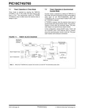
7.0 TIMER1 MODULE
The Timer1 module is a 16-bit timer/counter consisting
of two 8-bit registers (TMR1H and TMR1L), which are
readable and writable. The TMR1 Register pair
(TMR1H:TMR1L) increments from 0000h to FFFFh
and rolls over to 0000h. The TMR1 interrupt, if enabled,
is generated on overflow, which is latched in interrupt
flag bit TMR1IF (PIR1<0>). This interrupt can be
enabled/disabled by setting/clearing TMR1 interrupt
enable bit TMR1IE (PIE1<0>).
Timer1 can operate in one of two modes:
•As a timer
•As a counter
The operating mode is determined by the clock select
bit, TMR1CS (T1CON<1>).
In timer mode, Timer1 increments every instruction
cycle. In counter mode, it increments on every rising
edge of the external clock input.
Timer1 can be enabled/disabled by setting/clearing
control bit TMR1ON (T1CON<0>).
Timer1 also has an internal “RESET input”. This
RESET can be generated by either of the two CCP
modules (Section 9.0). Register 7-1 shows the Timer1
control register.
When the Timer1 oscillator is enabled (T1OSCEN is
set), the RC1/T1OSI/CCP2 and RC0/T1OSO/T1CKI
pins become inputs. That is, the TRISC<1:0> value is
ignored.
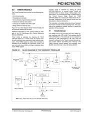
Additional information on timer modules is available in
the PIC Mid-Range MCU Family Reference Manual
(DS33023).
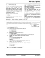
REGISTER 7-1: TIMER1 CONTROL REGISTER (T1CON: 10h)
U-0 U-0 R/W-0 R/W-0 R/W-0 R/W-0 R/W-0 R/W-0
— — T1CKPS1 T1CKPS0 T1OSCEN T1SYNC TMR1CS TMR1ON
R = Readable bit
W = Writable bit
U = Unimplemented bit,
read as ‘0’
- n = Value at POR reset
bit7 bit0
bit 7-6: Unimplemented: Read as '0'
bit 5-4: T1CKPS<1:0>: Timer1 Input Clock Prescale Select bits
11 = 1:8 Prescale value
10 = 1:4 Prescale value
01 = 1:2 Prescale value
00 = 1:1 Prescale value
bit 3: T1OSCEN: Timer1 Oscillator Enable Control bit
1 = Oscillator is enabled
0 = Oscillator is shut off (The oscillator inverter is turned off to eliminate power drain)
bit 2: T1SYNC
: Timer1 External Clock Input Synchronization Control bit
TMR1CS = 1
1 = Do not synchronize external clock input
0 = Synchronize external clock input
T
MR1CS = 0
This bit is ignored. Timer1 uses the internal clock when TMR1CS = 0.
bit 1: TMR1CS: Timer1 Clock Source Select bit
1 = External clock from pin RC0/T1OSO/T1CKI
(1)
or RC1/T1OSI/CCP2
0 = Internal clock (F
INT)
bit 0: TMR1ON: Timer1 On bit
1 = Enables Timer1
0 = Stops Timer1
Note 1: On the rising edge after the first falling edge.
器件 Datasheet 文档搜索
AiEMA 数据库涵盖高达 72,405,303 个元件的数据手册,每天更新 5,000 多个 PDF 文件
