Datasheet 搜索 > Microchip(微芯) > PIC16F1823T-E/ST 数据手册 > PIC16F1823T-E/ST 数据手册 200/398 页

 器件3D模型
¥ 6.131
PIC16F1823T-E/ST 数据手册 - Microchip(微芯)
制造商:
Microchip(微芯)
封装:
TSSOP
描述:
8月14日引脚闪存单片机采用nanoWatt XLP技术 8/14-Pin Flash Microcontrollers with nanoWatt XLP Technology
Pictures:
3D模型
符号图
焊盘图
引脚图
产品图
页面导航:
引脚图在P13P14P15P16P17P127P200P202P209P316Hot
典型应用电路图在P317
原理图在P12P20P55P66P75P99P127P131P133P149P154P160
封装尺寸在P373
标记信息在P371P372
封装信息在P371P382
功能描述在P307
技术参数、封装参数在P57P61P87P104P131P134P144P147P163P164P170P259
应用领域在P53P57P58P211P217
电气规格在P57P61P87P131P134P144P147P163P164P170P310
导航目录
PIC16F1823T-E/ST数据手册
Page:
of 398 Go
若手册格式错乱,请下载阅览PDF原文件
PIC12F/LF1822/16F/LF1823
DS41413A-page 200 Preliminary 2010 Microchip Technology Inc.
23.1 Capture Mode
Capture mode makes use of the 16-bit Timer1
resource. When an event occurs on the CCP1 pin, the
16-bit CCPR1H:CCPR1L register pair captures and
stores the 16-bit value of the TMR1H:TMR1L register
pair, respectively. An event is defined as one of the
following and is configured by the CCP1M<3:0> bits of
the CCP1CON register:
• Every falling edge
• Every rising edge
• Every 4th rising edge
• Every 16th rising edge
When a capture is made, the Interrupt Request Flag bit
CCP1IF of the PIR1 register is set. The interrupt flag
must be cleared in software. If another capture occurs
before the value in the CCPR1H, CCPR1L register pair
is read, the old captured value is overwritten by the new
captured value.
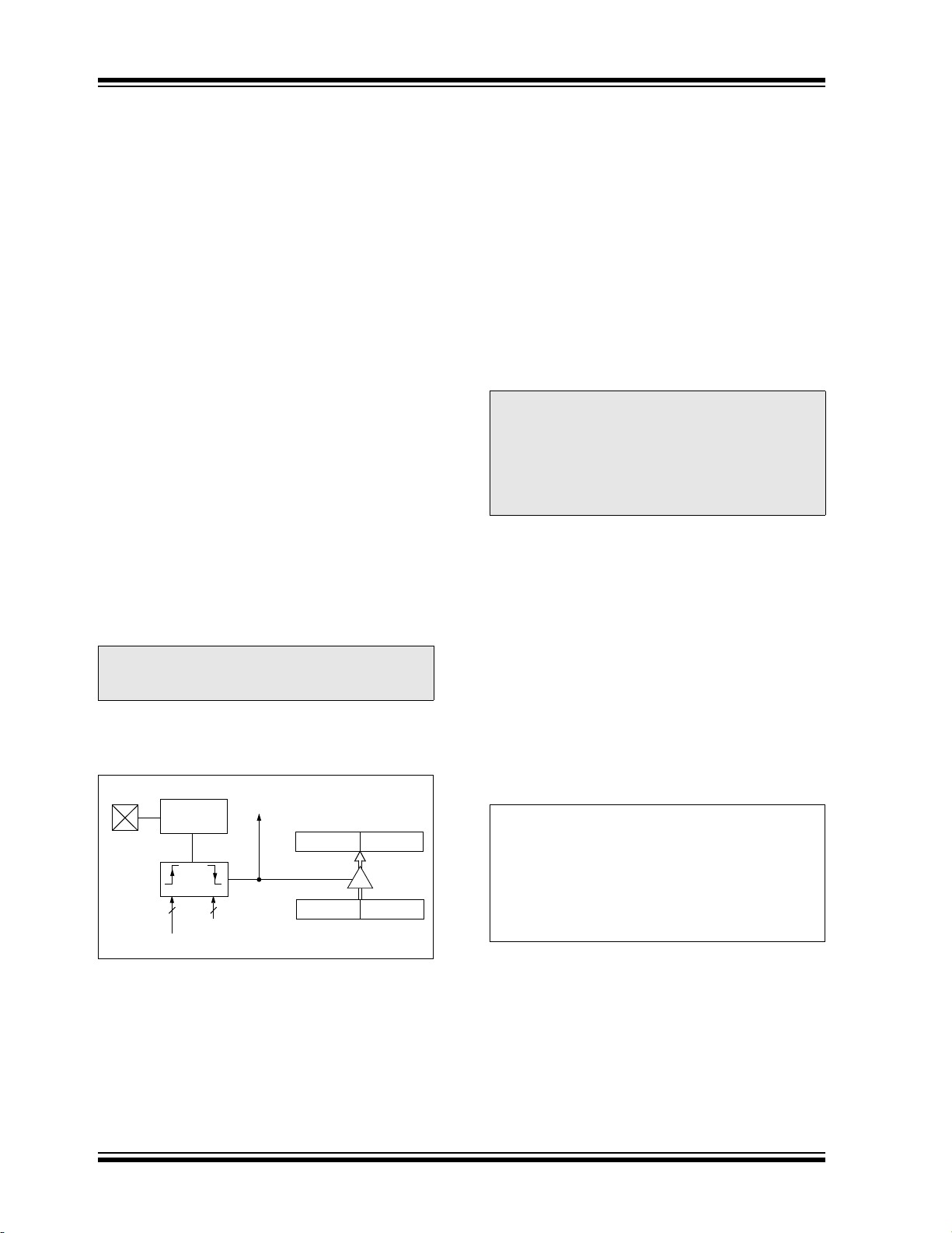
Figure 23-1 shows a simplified diagram of the Capture
operation.
23.1.1 CCP1 PIN CONFIGURATION
In Capture mode, the CCP1 pin should be configured
as an input by setting the associated TRIS control bit.
Also, the CCP1 pin function may be moved to
alternative pins using the APFCON register. Refer to
Section 12.1 “Alternate Pin Function” for more
details.
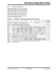
FIGURE 23-1: CAPTURE MODE
OPERATION BLOCK
DIAGRAM
23.1.2 TIMER1 MODE RESOURCE
Timer1 must be running in Timer mode or Synchronized
Counter mode for the CCP1 module to use the capture
feature. In Asynchronous Counter mode, the capture
operation may not work.
See Section 20.0 “Timer1 Module with Gate Control”
for more information on configuring Timer1.
23.1.3 SOFTWARE INTERRUPT MODE
When the Capture mode is changed, a false capture
interrupt may be generated. The user should keep the
CCP1IE interrupt enable bit of the PIE1 register clear to
avoid false interrupts. Additionally, the user should
clear the CCP1IF interrupt flag bit of the PIR1 register
following any change in Operating mode.
23.1.4 CCP1 PRESCALER
There are four prescaler settings specified by the
CCP1M<3:0> bits of the CCP1CON register.
Whenever the CCP1 module is turned off, or the CCP1
module is not in Capture mode, the prescaler counter
is cleared. Any Reset will clear the prescaler counter.
Switching from one capture prescaler to another does not
clear the prescaler and may generate a false interrupt. To
avoid this unexpected operation, turn the module off by
clearing the CCP1CON register before changing the
prescaler. Example 23-1 demonstrates the code to
perform this function.
EXAMPLE 23-1: CHANGING BETWEEN
CAPTURE PRESCALERS
Note: If the CCP1 pin is configured as an output,
a write to the port can cause a capture
condition.
CCPR1H CCPR1L
TMR1H TMR1L
Set Flag bit CCP1IF
(PIR1 register)
Capture
Enable
CCP1M<3:0>
Prescaler
1, 4, 16
and
Edge Detect
pin
CCP1
System Clock (F
OSC)
Note: Clocking Timer1 from the system clock
(F
OSC) should not be used in Capture
mode. In order for Capture mode to
recognize the trigger event on the CCP1
pin, Timer1 must be clocked from the
instruction clock (FOSC/4) or from an
external clock source.
BANKSEL CCP1CON ;Set Bank bits to point
;to CCP1CON
CLRF CCP1CON ;Turn CCP1 module off
MOVLW NEW_CAPT_PS ;Load the W reg with
;the new prescaler
;move value and CCP1 ON
MOVWF CCP1CON ;Load CCP1CON with this
;value
器件 Datasheet 文档搜索
AiEMA 数据库涵盖高达 72,405,303 个元件的数据手册,每天更新 5,000 多个 PDF 文件
