Datasheet 搜索 > 微控制器 > Microchip(微芯) > PIC18LF4620T-I/PT 数据手册 > PIC18LF4620T-I/PT 数据手册 123/412 页
 器件3D模型
¥ 61.645
PIC18LF4620T-I/PT 数据手册 - Microchip(微芯)
制造商:
Microchip(微芯)
分类:
微控制器
封装:
TQFP-44
描述:
PIC18 系列 3968 B RAM 64 kB 闪存 8位 增强型 微控制器 - TQFP-44
Pictures:
3D模型
符号图
焊盘图
引脚图
产品图
页面导航:
引脚图在P4P5P142P143P144P150Hot
典型应用电路图在P167
原理图在P10P12P13P27P43P108P126P130P136P138P143P144
封装尺寸在P387
标记信息在P385P386
封装信息在P385
技术参数、封装参数在P338P340P343P344P345
应用领域在P154P248
电气规格在P9P10P75P236P237P241P242P245


导航目录
PIC18LF4620T-I/PT数据手册
Page:
of 412 Go
若手册格式错乱,请下载阅览PDF原文件

© 2008 Microchip Technology Inc. DS39626E-page 121
PIC18F2525/2620/4525/4620
10.6 INTx Pin Interrupts
External interrupts on the RB0/INT0, RB1/INT1 and
RB2/INT2 pins are edge-triggered. If the corresponding
INTEDGx bit in the INTCON2 register is set (= 1), the
interrupt is triggered by a rising edge; if the bit is clear,
the trigger is on the falling edge. When a valid edge
appears on the RBx/INTx pin, the corresponding flag
bit, INTxIF, is set. This interrupt can be disabled by
clearing the corresponding enable bit, INTxIE. Flag bit,
INTxIF, must be cleared in software in the Interrupt
Service Routine before re-enabling the interrupt.
All external interrupts (INT0, INT1 and INT2) can wake-
up the processor from Idle or Sleep modes if bit INTxIE
was set prior to going into those modes. If the Global
Interrupt Enable bit, GIE, is set, the processor will
branch to the interrupt vector following wake-up.
Interrupt priority for INT1 and INT2 is determined by
the value contained in the interrupt priority bits,
INT1IP (INTCON3<6>) and INT2IP (INTCON3<7>).
There is no priority bit associated with INT0. It is
always a high-priority interrupt source.
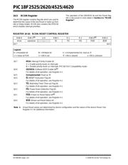
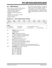
10.7 TMR0 Interrupt
In 8-bit mode (which is the default), an overflow in the
TMR0 register (FFh → 00h) will set flag bit, TMR0IF. In
16-bit mode, an overflow in the TMR0H:TMR0L
register pair (FFFFh → 0000h) will set TMR0IF. The
interrupt can be enabled/disabled by setting/clearing
enable bit, TMR0IE (INTCON<5>). Interrupt priority for
Timer0 is determined by the value contained in the
interrupt priority bit, TMR0IP (INTCON2<2>). See
Section 11.0 “Timer0 Module” for further details on
the Timer0 module.
10.8 PORTB Interrupt-on-Change
An input change on PORTB<7:4> sets flag bit, RBIF
(INTCON<0>). The interrupt can be enabled/disabled
by setting/clearing enable bit, RBIE (INTCON<3>).
Interrupt priority for PORTB interrupt-on-change is
determined by the value contained in the interrupt
priority bit, RBIP (INTCON2<0>).
10.9 Context Saving During Interrupts
During interrupts, the return PC address is saved on
the stack. Additionally, the WREG, STATUS and BSR
registers are saved on the Fast Return Stack. If a fast
return from interrupt is not used (see Section 5.3
“Data Memory Organization”), the user may need to
save the WREG, STATUS and BSR registers on entry
to the Interrupt Service Routine. Depending on the
user’s application, other registers may also need to be
saved. Example 10-1 saves and restores the WREG,
STATUS and BSR registers during an Interrupt Service
Routine.
EXAMPLE 10-1: SAVING STATUS, WREG AND BSR REGISTERS IN RAM
MOVWF W_TEMP ; W_TEMP is in virtual bank
MOVFF STATUS, STATUS_TEMP ; STATUS_TEMP located anywhere
MOVFF BSR, BSR_TEMP ; BSR_TMEP located anywhere
;
; USER ISR CODE
;
MOVFF BSR_TEMP, BSR ; Restore BSR
MOVF W_TEMP, W ; Restore WREG
MOVFF STATUS_TEMP, STATUS ; Restore STATUS
器件 Datasheet 文档搜索
AiEMA 数据库涵盖高达 72,405,303 个元件的数据手册,每天更新 5,000 多个 PDF 文件
