Datasheet 搜索 > 接口芯片 > TI(德州仪器) > TRS232ECDR 数据手册 > TRS232ECDR 数据手册 4/10 页
 器件3D模型
¥ 7.529
TRS232ECDR 数据手册 - TI(德州仪器)
制造商:
TI(德州仪器)
分类:
接口芯片
封装:
SOIC-16
描述:
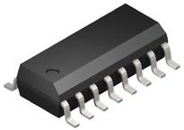
TEXAS INSTRUMENTS TRS232ECDR 线路接收器, RS232, 2驱动器, 4.5V-5.5电源, SOIC-16
Pictures:
3D模型
符号图
焊盘图
引脚图
产品图
页面导航:
引脚图在P2Hot
导航目录
TRS232ECDR数据手册
Page:
of 10 Go
若手册格式错乱,请下载阅览PDF原文件

4
Detailed Description
The HIN232A is a high-speed RS-232 transmitter/receiver
that is powered by a single +5V power supply, features low
power consumption, and meets all ElA RS232C and V.28
specifications. The circuit is divided into three sections: the
charge pump, transmitter, and receiver.
Charge Pump
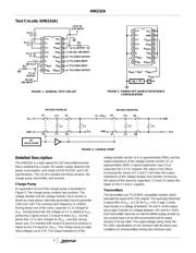
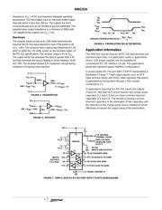
An equivalent circuit of the charge pump is illustrated in
Figure 3. The charge pump contains two sections: The
voltage doubler and the voltage inverter. Each section is
driven by a two phase, internally generated clock to generate
+10V and -10V. The nominal clock frequency is 125kHz.
During phase one of the clock, capacitor C1 is charged to
V
CC
. During phase two, the voltage on C1 is added to V
CC
,
producing a signal across C3 equal to twice V
CC
. During
phase two, C2 is also charged to 2V
CC
, and then during
phase one, it is inverted with respect to ground to produce a
signal across C4 equal to -2V
CC
. The charge pump accepts
input voltages up to 5.5V. The output impedance of the
voltage doubler section (V+) is approximately 200Ω, and the
output impedance of the voltage inverter section (V-) is
approximately 450Ω. A typical application uses 0.1µF
capacitors for C1-C4, however, the value is not critical.
Increasing the values of C1 and C2 will lower the output
impedance of the voltage doubler and inverter, increasing
the values of the reservoir capacitors, C3 and C4, lowers the
ripple on the V+ and V- supplies.
Transmitters
The transmitters are TTL/CMOS compatible inverters which
translate the inputs to RS-232 outputs. The input logic threshold
is about 26% of V
CC
, or 1.3V for V
CC
= 5V. A logic 1 at the
input results in a voltage of between -5V and V- at the output,
and a logic 0 results in a voltage between +5V and (V+ -0.6V).
Each transmitter input has an internal 400kΩ pullup resistor so
any unused input can be left unconnected and its output
remains in its low state. The output voltage swing meets the
RS-232C specifications of ±5V minimum with the worst case
conditions of: all transmitters driving 3kΩ minimum load
Test Circuits (HIN232A)
FIGURE 1. GENERAL TEST CIRCUIT
FIGURE 2. POWER-OFF SOURCE RESISTANCE
CONFIGURATION
14
15
16
9
13
12
11
10
1
2
3
4
5
7
6
8
C1+
V+
C1-
C2+
C2-
V-
R2
IN
T2
OUT
V
CC
T1
OUT
R1
IN
R1
OUT
T1
IN
T2
IN
R2
OUT
GND
+4.5V TO
+5.5V INPUT
3kΩ
T1 OUTPUT
RS-232 ±30V INPUT
TTL/CMOS OUTPUT
TTL/CMOS INPUT
TTL/CMOS INPUT
TTL/CMOS OUTPUT
+
-
0.1µF
C3
+
-
0.1µF
C1
+
-
0.1µF
C2
+
-
0.1µF C4
3kΩ
OUTPUT
RS-232
±30V INPUT
T2
14
15
16
9
13
12
11
10
1
2
3
4
5
7
6
8
C1+
V+
C1-
C2+
C2-
V-
R2
IN
T2
OUT
V
CC
T1
OUT
R1
IN
R1
OUT
T1
IN
T2
IN
R2
OUT
GND
T2
OUT
T1
OUT
V
IN
= ±2V
A
R
OUT
= V
IN
/I
+
-
C1
+
-
C3
+
-
C2
+
-
C4
S1
S2
S5
S6
S3
S4
S7
S8
V
CC
GND
RC
OSCILLATOR
V
CC
GND
V+ = 2V
CC
GND
V- = - (V+)
C1+
C1-
C2-
C2+
VOLTAGE INVERTER
VOLTAGE DOUBLER
FIGURE 3. CHARGE PUMP
HIN232A
器件 Datasheet 文档搜索
AiEMA 数据库涵盖高达 72,405,303 个元件的数据手册,每天更新 5,000 多个 PDF 文件
