Datasheet 搜索 > FET驱动器 > TI(德州仪器) > UCC27511DBVR 数据手册 > UCC27511DBVR 数据手册 26/39 页

¥ 2.644
UCC27511DBVR 数据手册 - TI(德州仪器)
制造商:
TI(德州仪器)
分类:
FET驱动器
封装:
SOT-23-6
描述:
TEXAS INSTRUMENTS UCC27511DBVR 驱动器, IGBT, MOSFET, 低压侧, 4.5V-18V电源, 8A输出, -999ms 延迟, SOT-23-6
Pictures:
3D模型
符号图
焊盘图
引脚图
产品图
页面导航:
引脚图在P5P6Hot
典型应用电路图在P1P22P23P24P25P26
原理图在P15P16P17
封装尺寸在P30P32P33
标记信息在P30
封装信息在P7P29P30P31P32P33
功能描述在P4P5
技术参数、封装参数在P7
应用领域在P1P31P39
电气规格在P4P9P19P23
型号编号列表在P4

导航目录
UCC27511DBVR数据手册
Page:
of 39 Go
若手册格式错乱,请下载阅览PDF原文件
OFF ON
SW G SW
OFF GATE ON GATE
R R
P 0.5 Q VDD f
R R R R
æ ö
= ´ ´ ´ ´ +
ç ÷
+ +
è ø
UCC27511
,
UCC27512
SLUSAW9F –FEBRUARY 2012–REVISED NOVEMBER 2014
www.ti.com
Typical Application (continued)
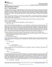
This power P
G
is dissipated in the resistive elements of the circuit when the MOSFET/IGBT is being turned on or
off. Half of the total power is dissipated when the load capacitor is charged during turnon, and the other half is
dissipated when the load capacitor is discharged during turnoff. When no external gate resistor is employed
between the driver and MOSFET/IGBT, this power is completely dissipated inside the driver package. With the
use of external gate-drive resistors, the power dissipation is shared between the internal resistance of driver and
external gate resistor in accordance to the ratio of the resistances (more power dissipated in the higher
resistance component). Based on this simplified analysis, the driver power dissipation during switching is
calculated in Equation 5.
where
• R
OFF
= R
OL
• R
ON
(effective resistance of pull-up structure) = 2.7 x R
OL
(5)
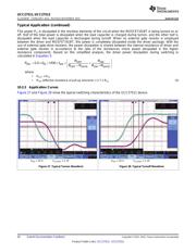
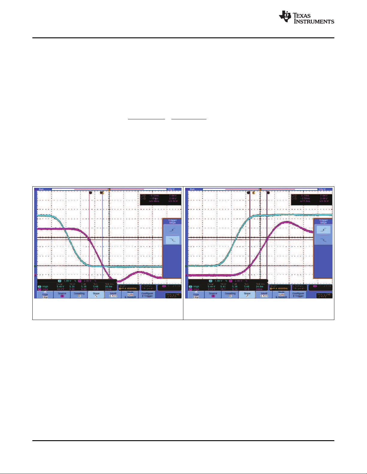
10.2.3 Application Curves
Figure 27 and Figure 28 show the typical switching characteristics of the UCC27511 device.
V
DD
= 10 V C
(LOAD)
= 1 nF V
DD
= 10 V C
(LOAD)
= 1 nF
Figure 27. Typical Turnon Waveform Figure 28. Typical Turnoff Waveform
26 Submit Documentation Feedback Copyright © 2012–2014, Texas Instruments Incorporated
Product Folder Links: UCC27511 UCC27512
器件 Datasheet 文档搜索
AiEMA 数据库涵盖高达 72,405,303 个元件的数据手册,每天更新 5,000 多个 PDF 文件
