Datasheet 搜索 > FET驱动器 > TI(德州仪器) > UCC27517ADBVR 数据手册 > UCC27517ADBVR 数据手册 13/31 页

¥ 1.932
UCC27517ADBVR 数据手册 - TI(德州仪器)
制造商:
TI(德州仪器)
分类:
FET驱动器
封装:
SOT-23-5
描述:
具有 5V UVLO 和负输入电压处理能力的 4A/4A 单通道栅极驱动器 5-SOT-23 -40 to 125
Pictures:
3D模型
符号图
焊盘图
引脚图
产品图
页面导航:
引脚图在P4Hot
典型应用电路图在P1P13P16P17
原理图在P12P13
封装尺寸在P25P27P28
标记信息在P25
封装信息在P4P24P25P26P27P28
功能描述在P11
技术参数、封装参数在P4
应用领域在P1P31
电气规格在P6P14
型号编号列表在P3
导航目录
UCC27517ADBVR数据手册
Page:
of 31 Go
若手册格式错乱,请下载阅览PDF原文件

UCC27517A
www.ti.com
SLUSBQ0C – AUGUST 2013–REVISED AUGUST 2015
Feature Description (continued)
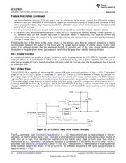
9.3.2 Operating Supply Current
The UCC27517A features very low quiescent I
DD
currents. The typical operating-supply current in Undervoltage-
Lockout (UVLO) state and fully-on state (under static and switching conditions) are summarized in Figure 6,
Figure 6 and Figure 7. The I
DD
current when the device is fully on and outputs are in a static state (DC high or
DC low, refer Figure 5) represents lowest quiescent I
DD
current when all the internal logic circuits of the device
are fully operational. The total supply current is the sum of the quiescent I
DD
current, the average I
OUT
current
due to switching and finally any current related to pullup resistors on the unused input pin. For example when the
inverting input pin is pulled low additional current is drawn from V
DD
supply through the pull-up resistors (refer to
Detailed Description for the device Block Diagram). Knowing the operating frequency (f
SW
) and the MOSFET
gate (Q
G
) charge at the drive voltage being used, the average I
OUT
current can be calculated as product of Q
G
and f
SW
.
A complete characterization of the I
DD
current as a function of switching frequency at different V
DD
bias voltages
under 1.8-nF switching load is provided in Figure 15. The strikingly-linear variation and close correlation with
theoretical value of average I
OUT
indicates negligible shoot-through inside the gate-driver device attesting to the
high-speed characteristics of I
OUT
.
9.3.3 Input Stage
The input pins of the UCC27517A are based on a TTL and CMOS compatible input-threshold logic that is
independent of the V
DD
supply voltage. With typical high threshold = 2.2 V and typ low threshold = 1.2 V, the
logic-level thresholds can be conveniently driven with PWM-control signals derived from 3.3-V and 5-V digital-
power controllers. Wider hysteresis (typically 1 V) offers enhanced noise immunity compared to traditional TTL-
logic implementations, where the hysteresis is typically less than 0.5 V. These devices also feature tight control
of the input-pin threshold-voltage levels which eases system-design considerations and ensures stable operation
across temperature. The very low input capacitance on these pins reduces loading and increases switching
speed.
The device features an important protection function wherein, whenever any of the input pins are in a floating
condition, the output of the respective channel is held in the low state. This is achieved using V
DD
-pullup resistors
on all the inverting inputs (IN– pin) or GND-pulldown resistors on all the non-inverting input pins (IN+ pin), (refer
to Functional Block Diagram section).
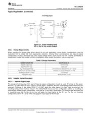
The device also features a dual-input configuration with two input pins available to control the state of the output.
The user has the flexibility to drive the device using either a non-inverting input pin (IN+) or an inverting input pin
(IN–). The state of the output pin is dependent on the bias on both the IN+ and IN– pins. Refer to the input/output
logic truth table (Table 4) and the Typical Application Diagrams, (Figure 22 and Figure 23), for additional
clarification.
Once an input pin has been chosen for PWM drive, the other input pin (the unused input pin) must be properly
biased in order to enable the output. As mentioned earlier, the unused input pin cannot remain in a floating
condition because, whenever any input pin is left in a floating condition, the output is disabled for protection
purposes. Alternatively, the unused input pin can effectively be used to implement an enable/disable function, as
explained below.
• In order to drive the device in a non-inverting configuration, apply the PWM-control input signal to IN+ pin. In
this case, the unused input pin, IN–, must be biased low (eg. tied to GND) in order to enable the output.
– Alternately, the IN– pin can be used to implement the enable/disable function using an external logic
signal. OUT is disabled when IN– is biased high and OUT is enabled when IN – is biased low.
• In order to drive the device in an inverting configuration, apply the PWM-control input signal to IN– pin. In this
case, the unused input pin, IN+, must be biased high (eg. tied to V
DD
) in order to enable the output.
– Alternately, the IN+ pin can be used to implement the enable/disable function using an external logic
signal. OUT is disabled when IN+ is biased low and OUT is enabled when IN+ is biased high.
• Finally, note that the output pin is driven into a high state only when IN+ pin is biased high and IN– input is
biased low.
The input stage of the driver should preferably be driven by a signal with a short rise or fall time. Caution must be
exercised whenever the driver is used with slowly-varying input signals, especially in situations where the device
is located in a mechanical socket or PCB layout is not optimal:
• High dI/dt current from the driver output coupled with board layout parasitics causes ground bounce. Because
Copyright © 2013–2015, Texas Instruments Incorporated Submit Documentation Feedback 13
Product Folder Links: UCC27517A
器件 Datasheet 文档搜索
AiEMA 数据库涵盖高达 72,405,303 个元件的数据手册,每天更新 5,000 多个 PDF 文件
