Datasheet 搜索 > 稳压芯片 > TI(德州仪器) > UCC28950PWR 数据手册 > UCC28950PWR 数据手册 17/74 页
 器件3D模型
¥ 10.515
UCC28950PWR 数据手册 - TI(德州仪器)
制造商:
TI(德州仪器)
分类:
稳压芯片
封装:
TSSOP-24
描述:
绿色环保相移全桥控制器采用同步整流 Green Phase-Shifted Full-Bridge Controller With Synchronous Rectification
Pictures:
3D模型
符号图
焊盘图
引脚图
产品图
页面导航:
引脚图在P4Hot
典型应用电路图在P1P37
原理图在P15P17P61P62
封装尺寸在P68P70P71
焊盘布局在P32
标记信息在P68
封装信息在P5P67P68P69P70P71
技术参数、封装参数在P5
应用领域在P1P74
电气规格在P6P7
导航目录
UCC28950PWR数据手册
Page:
of 74 Go
若手册格式错乱,请下载阅览PDF原文件

SS
SS(slave)
T
C
20.6
825k Ln
20.6 – 0.55 – EA+
=
æ ö
´
ç ÷
è ø
(
SS
SS(master )
T 25 A
C
0.55
´ m
=
+
)
EA+
UCC28950
www.ti.com
SLUSA16C –MARCH 2010–REVISED NOVEMBER 2015
Feature Description (continued)
7.3.4 Soft Start and Enable (SS/EN)
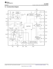
The soft-start pin SS/EN is a multi-function pin used for the following operations:
• Closed loop soft start with the gradual duty cycle increase from the minimum set by TMIN up to the steady
state duty cycle required by the regulated output voltage.
• Setting hiccup mode conditions during cycle-by-cycle overcurrent limit.
• On/off control for the converter.
During soft start, one of the voltages at the SS/EN or EA+ pins, whichever is lower (SS/EN – 0.55 V) or EA+
voltage (see Block Diagram), sets the reference voltage for a closed feedback loop. Both SS/EN and EA+ signals
are non-inverting inputs of the error amplifier with the COMP pin being its output. Thus the soft start always goes
under the closed feedback loop and the voltage at COMP pin sets the duty cycle. The duty cycle defined by the
COMP pin voltage can not be shorter than TMIN pulse width set by the user. However, if the shortest duty cycle
is set by the cycle-by-cycle current limit circuit, then it becomes dominant over the duty cycle defined by the
COMP pin voltage or by the TMIN block.
The soft-start duration is defined by an external capacitor C
SS
, connected between the SS/EN pin and ground,
and the internal charge current that has a typical value of 25 µA. Pulling the soft-start pin externally below 0.55 V
shuts down the controller. The release of the soft-start pin enables the controller to start, and if there is no
current limit condition, the duty cycle applied to the output inductor gradually increases until it reaches the steady
state duty cycle defined by the regulated output voltage of the converter. This happens when the voltage at the
SS/EN pin reaches and then exceeds by 0.55 V, the voltage at the EA+ pin. Thus for the given soft-start time
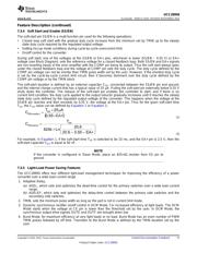
T
SS
, the C
SS
value can be defined by Equation 1 or Equation 2:
(1)
(2)
For example, in Equation 1, if the soft-start time T
SS
is selected to be 10 ms, and the EA+ pin is 2.5 V, then the
soft-start capacitor C
SS
is equal to 82 nF.
NOTE
If the converter is configured in Slave Mode, place an 825-kΩ resistor from SS pin to
ground.
7.3.5 Light-Load Power Saving Features
The UCC28950 offers four different light-load management techniques for improving the efficiency of a power
converter over a wide load current range.
1. Adaptive Delay,
(a) ADEL, which sets and optimizes the dead-time control for the primary switches over a wide load current
range.
(b) ADELEF, which sets and optimizes the delay-time control between the primary side switches and the
secondary side switches.
2. TMIN, sets the minimum pulse width as long as the part is not in current limit mode.
3. Dynamic synchronous rectifier on/off control in DCM Mode, For increased efficiency at light loads. The DCM
Mode starts when the voltage at CS pin is lower than the threshold set by the user. In DCM Mode, the
synchronous output drive signals OUTE and OUTF are brought down low.
4. Burst Mode, for maximum efficiency at very light loads or no load. Burst Mode has an even number of PWM
TMIN pulses followed by off time. Transition to the Burst Mode is defined by the TMIN duration set by the
user.
Copyright © 2010–2015, Texas Instruments Incorporated Submit Documentation Feedback 17
Product Folder Links: UCC28950
器件 Datasheet 文档搜索
AiEMA 数据库涵盖高达 72,405,303 个元件的数据手册,每天更新 5,000 多个 PDF 文件
