Datasheet 搜索 > Microchip(微芯) > UPS120EE3/TR7 数据手册 > UPS120EE3/TR7 数据手册 2/4 页

¥ 1.155
UPS120EE3/TR7 数据手册 - Microchip(微芯)
制造商:
Microchip(微芯)
封装:
-
Pictures:
3D模型
符号图
焊盘图
引脚图
产品图
页面导航:


导航目录
UPS120EE3/TR7数据手册
Page:
of 4 Go
若手册格式错乱,请下载阅览PDF原文件
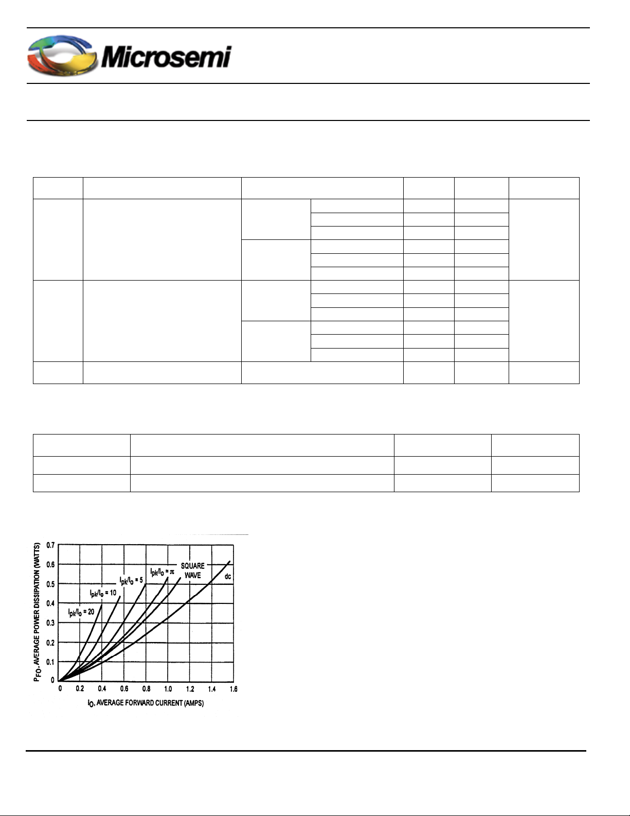
Low Leakage Schottky Barrier Rectifier
www.Microsemi.com
2/4
Copyright © 2008
June 2008 Rev E
UPS120Ee3
Characteristics
Static Electrical Characteristics
Symbol Parameter Test Conditions Typ max Units
I
F
= 0.1 A 0.455
I
F
= 1.0 A 0.530
T
J
= 25ºC
I
F
= 3.0 A 0.595
I
F
= 0.1 A 0.360
I
F
= 1.0 A 0.455
V
F
(2)
Maximum forward voltage
T
J
= 100ºC
I
F
= 3.0 A 0.540
V
V
R
= 20V 10
V
R
= 10V 1.0
T
J
= 25ºC
V
R
= 5V 0.5
V
R
= 20V 1600
V
R
= 10V 500
I
R
(2)
Maximum instantaneous
reverse current
T
J
= 100ºC
V
R
= 5V 300
µA
C
T
Junction capacitance V
R
= 5V, f = 1MHz pF
(2)
Measured with a test pulse of 380µs to minimize self-heating effect
Thermal Characteristics
Symbol Parameter Value Unit
R
ΘJC
Junction to case (bottom) 15 ºC/W
R
ΘJA
Junction to ambient
(3)
240 ºC/W
(3)
Mounted on FR-4 PC board using 1oz copper with recommended minimum foot print
Reverse power dissipation and the possibility of thermal runaway
must be considered when operating this device under any
reverse voltage conditions. Calculations of T
J
therefore must
include forward and reverse power effects. The allowable
operating T
J
may be calculated from the equation:
T
J
= T
J max
= r(t)(Pf+Pr) where
r(t) = thermal impedance under given conditions.
Pf = forward power dissipation, and
Pr = reverse power dissipation
This graph displays the de-rated allowable T
J
due to reverse bias
under DC conditions only and is calculated as T
J
= T
J max
-r(t) Pr,
Where r(t)=Rthja. For other power applications further
calculations must be performed.
器件 Datasheet 文档搜索
AiEMA 数据库涵盖高达 72,405,303 个元件的数据手册,每天更新 5,000 多个 PDF 文件
