Datasheet 搜索 > LVDS、M-LVDS、ECL、CML > TI(德州仪器) > SN65LV1224ADBRG4 数据手册 > SN65LV1224ADBRG4 其他数据使用手册 1/2 页
 器件3D模型
¥ 10.412
SN65LV1224ADBRG4 其他数据使用手册 - TI(德州仪器)
制造商:
TI(德州仪器)
分类:
LVDS、M-LVDS、ECL、CML
封装:
SSOP-28
Pictures:
3D模型
符号图
焊盘图
引脚图
产品图
SN65LV1224ADBRG4数据手册
Page:
of 2 Go
若手册格式错乱,请下载阅览PDF原文件

Printed in U.S.A 1
!"#$ %
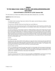
This document is an errata to the SN65LV1224A data sheet (Literature No. SLLS570A).
Applies to
SN65LV1224A devices.
Problem:
The SN65LV1224A sometimes “false locks” with the SYNC pattern under the following conditions:
1) POWERDNB toggling and
2) Asynchronous operation (Refclk and Serial Data have a ppm difference)
The “false lock” means that observing only the LOCKN signal being low, which should be an indication of the
device having found a proper byte boundary can be deceptive until the data on the parallel bus is actually
examined for verification.
One way to monitor this is to look at the LOCKN pin in infinite persistence mode on the oscilloscope and monitor
Rout 4 on the parallel data using SYNC pattern as a serial input. ROUT4 should be ”1” with a SYNC pattern,
but on False Lock, this bit becomes ”0”. The device eventually is found (by lab experiments) to recover from this
false lock condition on its own but the recovery time sometimes exceed the LOCK time specified on the data
sheet. However, whenever the device recovers from this “false lock” state, LOCKN signal sometimes goes high
and low for a brief moment. In summary, this false lock phenomenon is very random and rare in nature and does
not occur on every power cycle.
Solution:
One solution would be:
According to the data sheet, with the SYNC pattern as an input, the device should lock to the input within 815
reference clock cycles upon power up. Based on that specification, a user can send 795 Parallel clock cycles
of “1010” Data followed by 20 (795+20=815) parallel clock cycles of the SYNC pattern. The Transitions in the
1010 pattern was found to help the CDR to lock to the incoming data properly.
Second solution would be:
So far in our lab testing, the device has never “false locked” to an input pattern with some degree of randomness
(vs. repeating SYNC pattern of 111111000000). Therefore one solution would be just to have the device left to
“random lock” to incoming data stream assuming the incoming data has some degree of randomness in it. The
“random lock” capability of the device is discussed in the datasheet.
Third solution would be:
The device was found to be never “false lock” to the input pattern of 100000000000 or 11111111110 even if these
patterns repeat themselves. So a user can substitute either of these patterns for SYNC pattern.
器件 Datasheet 文档搜索
AiEMA 数据库涵盖高达 72,405,303 个元件的数据手册,每天更新 5,000 多个 PDF 文件
