Datasheet 搜索 > DA转换器 > ADI(亚德诺) > AD5693BCPZ-RL7 数据手册 > AD5693BCPZ-RL7 数据手册 5/16 页
 器件3D模型
¥ 13.452
AD5693BCPZ-RL7 数据手册 - ADI(亚德诺)
制造商:
ADI(亚德诺)
分类:
DA转换器
封装:
LFCSP-8
Pictures:
3D模型
符号图
焊盘图
引脚图
产品图
页面导航:
导航目录
AD5693BCPZ-RL7数据手册
Page:
of 16 Go
若手册格式错乱,请下载阅览PDF原文件
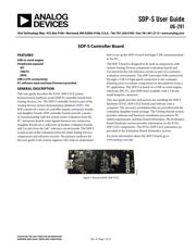
SDP-S User Guide UG-291
Rev. A | Page 5 of 16
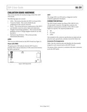
EVALUATION BOARD HARDWARE
This section describes the hardware design of the EVAL-SDP-
CS1Z board.
The following topics are covered:
• LEDs—This section describes the SDP-S on-board LEDs.
• Connector details—This section details the pin
assignments on the 120-pin connector.
• Power—This section lists power requirements of the SDP-S
and identifies connector power inputs and output pins.
• Daughter board design guidelines—This section provides
guidelines on how to design daughter boards for use with
the SDP-S.
• Mechanical specifications—This section provides
dimensional information.
LEDS
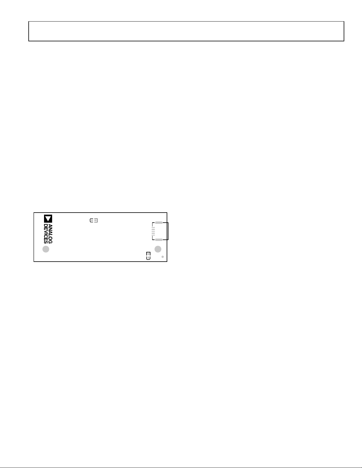
There are two LEDs located on the SDP-S board (see Figure 3).
Power LED (PWR)
The green power LED indicates that the SDP-S board is
powered. This is not an indication of USB connectivity between
the SDP-S and the PC.
LED1
Rev 1.0
SDP–S
PWR
J2
09916-003
Figure 3. SDP-S Board LEDs
LED1
The orange LED is an LED used as a diagnostic tool for
evaluation application developers.
CONNECTOR DETAILS
The SDP-S board contains one Hirose FX8-120P-SV1(91),
120-pin header connector. Through this connector, the
peripheral communication interfaces of the USB-to-serial
engine are exposed. The exposed peripherals are
• SPI
• I
2
C/TWI
• GPIO
Also included on the connector specification are input and out-
put power pins, ground pins, and pins reserved for future use.
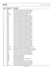
Connector Pin Assignments
Table 1 lists the connector pins and identifies the functionality
assigned to each connector pin on the SDP-S board.
The pinout of this connector is consistent with other connectors
across the SDP family.
器件 Datasheet 文档搜索
AiEMA 数据库涵盖高达 72,405,303 个元件的数据手册,每天更新 5,000 多个 PDF 文件
