Datasheet 搜索 > DC/DC转换器 > TI(德州仪器) > CSD95377Q4M 数据手册 > CSD95377Q4M 数据手册 3/21 页

¥ 6.261
CSD95377Q4M 数据手册 - TI(德州仪器)
制造商:
TI(德州仪器)
分类:
DC/DC转换器
封装:
VSON-Clip-8
描述:
20V 35A SON 3.5 x 4.5mm 同步降压 NexFET™ 功率级 8-VSON-CLIP -40 to 150
Pictures:
3D模型
符号图
焊盘图
引脚图
产品图
页面导航:
导航目录
CSD95377Q4M数据手册
Page:
of 21 Go
若手册格式错乱,请下载阅览PDF原文件
PWM
8
7
6
5
4
9
P
GND
1
V
IN
SKIP#
V
SW
V
DD
P
GND
BOOT
BOOT_R
2
3
3
CSD95377Q4M
www.ti.com.cn
ZHCSEI7 –DECEMBER 2015
Copyright © 2015, Texas Instruments Incorporated
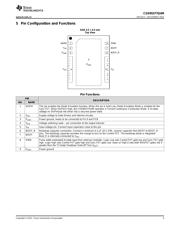
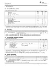
5 Pin Configuration and Functions
SON 3.5 × 4.5 mm
Top View
Pin Functions
PIN
DESCRIPTION
NO. NAME
1 SKIP# This pin enables the Diode Emulation function. When this pin is held Low, Diode Emulation Mode is enabled for the
Sync FET. When SKIP# is High, the CSD95377Q4M operates in Forced Continuous Conduction Mode. A tri-state
voltage on SKIP# puts the driver into a very-low power state.
2 V
DD
Supply voltage to Gate Drivers and internal circuitry
3 P
GND
Power ground, needs to be connected to Pin 9 and PCB
4 V
SW
Voltage switching node – pin connection to the output inductor
5 V
IN
Input voltage pin. Connect input capacitors close to this pin.
6 BOOT_R Bootstrap capacitor connection. Connect a minimum 0.1 µF 16 V X5R, ceramic capacitor from BOOT to BOOT_R
pins. The bootstrap capacitor provides the charge to turn on the Control FET. The bootstrap diode is integrated.
Boot_R is internally connected to V
SW
.
7 BOOT
8 PWM Pulse width modulated tri-state input from external controller. Logic Low sets Control FET gate low and Sync FET gate
high. Logic High sets Control FET gate high and Sync FET gate Low. Open or High-Z sets both MOSFET gates low if
greater than the Tri-State Shutdown Hold-off Time (t
3HT
)
9 P
GND
Power ground
器件 Datasheet 文档搜索
AiEMA 数据库涵盖高达 72,405,303 个元件的数据手册,每天更新 5,000 多个 PDF 文件
