Datasheet 搜索 > 微控制器 > TI(德州仪器) > LM3S6965-IQC50-A2T 数据手册 > LM3S6965-IQC50-A2T 数据手册 6/761 页
 器件3D模型
¥ 249.791
LM3S6965-IQC50-A2T 数据手册 - TI(德州仪器)
制造商:
TI(德州仪器)
分类:
微控制器
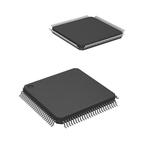
封装:
LQFP-100
描述:
的Stellaris LM3S6965微控制器 Stellaris LM3S6965 Microcontroller
Pictures:
3D模型
符号图
焊盘图
引脚图
产品图
页面导航:
引脚图在P160P172P336P396P433P476P514P551P599P612P650Hot
典型应用电路图在P47P610
原理图在P44P45P54P55P56P160P240P260P293P335P372P395
封装尺寸在P52P749P750P752P753P754P756P757P759P760
型号编码规则在P747
标记信息在P747P757P758
封装信息在P747P751P752P756P757P758P759P760
功能描述在P95P161P172P241P260P292P336P372P397P434P476P515
技术参数、封装参数在P699P701P702P703P705
应用领域在P44P58P179P761
电气规格在P52P700P702P704P706P708P710P712P714P716
导航目录
LM3S6965-IQC50-A2T数据手册
Page:
of 761 Go
若手册格式错乱,请下载阅览PDF原文件

9.3.2 32-Bit Timer Operating Modes ...................................................................................... 337
9.3.3 16-Bit Timer Operating Modes ...................................................................................... 338
9.4 Initialization and Configuration ..................................................................................... 342
9.4.1 32-Bit One-Shot/Periodic Timer Mode ........................................................................... 342
9.4.2 32-Bit Real-Time Clock (RTC) Mode ............................................................................. 343
9.4.3 16-Bit One-Shot/Periodic Timer Mode ........................................................................... 343
9.4.4 16-Bit Input Edge Count Mode ..................................................................................... 344
9.4.5 16-Bit Input Edge Timing Mode .................................................................................... 344
9.4.6 16-Bit PWM Mode ....................................................................................................... 345
9.5 Register Map .............................................................................................................. 345
9.6 Register Descriptions .................................................................................................. 346
10 Watchdog Timer ................................................................................................... 371
10.1 Block Diagram ............................................................................................................ 372
10.2 Functional Description ................................................................................................. 372
10.3 Initialization and Configuration ..................................................................................... 373
10.4 Register Map .............................................................................................................. 373
10.5 Register Descriptions .................................................................................................. 374
11 Analog-to-Digital Converter (ADC) ..................................................................... 395
11.1 Block Diagram ............................................................................................................ 395
11.2 Signal Description ....................................................................................................... 396
11.3 Functional Description ................................................................................................. 397
11.3.1 Sample Sequencers .................................................................................................... 397
11.3.2 Module Control ............................................................................................................ 397
11.3.3 Hardware Sample Averaging Circuit ............................................................................. 398
11.3.4 Analog-to-Digital Converter .......................................................................................... 398
11.3.5 Differential Sampling ................................................................................................... 399
11.3.6 Test Modes ................................................................................................................. 401
11.3.7 Internal Temperature Sensor ........................................................................................ 401
11.4 Initialization and Configuration ..................................................................................... 402
11.4.1 Module Initialization ..................................................................................................... 402
11.4.2 Sample Sequencer Configuration ................................................................................. 402
11.5 Register Map .............................................................................................................. 403
11.6 Register Descriptions .................................................................................................. 404
12 Universal Asynchronous Receivers/Transmitters (UARTs) ............................. 432
12.1 Block Diagram ............................................................................................................ 433
12.2 Signal Description ....................................................................................................... 433
12.3 Functional Description ................................................................................................. 434
12.3.1 Transmit/Receive Logic ............................................................................................... 434
12.3.2 Baud-Rate Generation ................................................................................................. 435
12.3.3 Data Transmission ...................................................................................................... 435
12.3.4 Serial IR (SIR) ............................................................................................................. 436
12.3.5 FIFO Operation ........................................................................................................... 437
12.3.6 Interrupts .................................................................................................................... 437
12.3.7 Loopback Operation .................................................................................................... 438
12.3.8 IrDA SIR block ............................................................................................................ 439
12.4 Initialization and Configuration ..................................................................................... 439
12.5 Register Map .............................................................................................................. 440
12.6 Register Descriptions .................................................................................................. 441
July 15, 20146
Texas Instruments-Production Data
Table of Contents
器件 Datasheet 文档搜索
AiEMA 数据库涵盖高达 72,405,303 个元件的数据手册,每天更新 5,000 多个 PDF 文件
