Datasheet 搜索 > 负载控制器 > Linear Technology(凌力尔特) > LT1160IS#TRPBF 数据手册 > LT1160IS#TRPBF 数据手册 10/16 页
 器件3D模型
¥ 30.144
LT1160IS#TRPBF 数据手册 - Linear Technology(凌力尔特)
制造商:
Linear Technology(凌力尔特)
分类:
负载控制器
封装:
SOIC-14
Pictures:
3D模型
符号图
焊盘图
引脚图
产品图
页面导航:

导航目录
LT1160IS#TRPBF数据手册
Page:
of 16 Go
若手册格式错乱,请下载阅览PDF原文件

10
LT1160/LT1162
11602fb
APPLICATIONS INFORMATION
WUU
U
The actual increase in supply current is slightly higher due
to LT1160 switching losses and the fact that the gates are
being charged to more than 10V. Supply Current vs
Input Frequency is given in the Typical Performance
Characteristics.
The LT1160 junction temperature can be estimated by
using the equations given in Note 2 of the Electrical
Characteristics. For example, the LT1160IS is limited to
less than 31mA from a 12V supply:
T
J
= 85°C + (31mA)(12V)(110°C/W)
= 126°C exceeds absolute maximum
In order to prevent the maximum junction temperature
from being exceeded, the LT1160 supply current must be
verified while driving the full complement of the chosen
MOSFET type at the maximum switching frequency.
Ugly Transient Issues
In PWM applications the drain current of the top MOSFET
is a square wave at the input frequency and duty cycle. To
prevent large voltage transients at the top drain, a low ESR
electrolytic capacitor must be used and returned to the
power ground. The capacitor is generally in the range of
25µF to 5000µF and must be physically sized for the RMS
current flowing in the drain to prevent heating and prema-
ture failure. In addition, the LT1160 requires a separate
10µF capacitor connected closely between Pins 1 and 5
(the LT1162 requires two 10µF capacitors connected
between Pins 1 and 5, and Pins 7 and 11).
The LT1160 top source is internally protected against
transients below ground and above supply. However, the
gate drive pins cannot be forced below ground. In most
applications, negative transients coupled from the source
to the gate of the top MOSFET do not cause any problems.
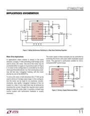
Switching Regulator Applications
The LT1160 (or 1/2 LT1162) is ideal as a synchronous
switch driver to improve the efficiency of step-down
(buck) switching regulators. Most step-down regulators
use a high current Schottky diode to conduct the inductor
current when the switch is off. The fractions of the oscil-
lator period that the switch is on (switch conducting) and
off (diode conducting) are given by:
Switch Total Period
Switch Total Period
ON =
V
HV
OFF =
HV – V
HV
OUT
OUT
⎛
⎝
⎜
⎞
⎠
⎟
()
⎛
⎝
⎜
⎞
⎠
⎟
()
Note that for HV
> 2V
OUT
the switch is off longer than it is
on, making the diode losses more significant than the
switch. The worst case for the diode is during a short
circuit, when V
OUT
approaches zero and the diode con-
ducts the short-circuit current almost continuously.
Figure 2 shows the LT1160 used to synchronously drive a
pair of power MOSFETs in a step-down regulator applica-
tion, where the top MOSFET is the switch and the bottom
MOSFET replaces the Schottky diode. Since both conduc-
tion paths have low losses, this approach can result in very
high efficiency (90% to 95%) in most applications. For
regulators under 10A, using low R
DS(ON)
N-channel
MOSFETs eliminates the need for heat sinks. R
GS
holds the
top MOSFET off when HV
is applied before the 12V supply.
One fundamental difference in the operation of a step-
down regulator with synchronous switching is that it never
becomes discontinuous at light loads. The inductor cur-
rent doesn’t stop ramping down when it reaches zero but
actually reverses polarity resulting in a constant ripple
current independent of load. This does not cause a signifi-
cant efficiency loss (as might be expected) since the
negative inductor current is returned to HV when the
switch turns back on. However, I
2
R losses will occur
under these conditions due to the recirculating currents.
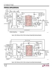
The LT1160 performs the synchronous MOSFET drive in a
step-down switching regulator. A reference and PWM are
required to complete the regulator. Any voltage mode or
current mode PWM controller may be used but the LT3526
is particularly well-suited to high power, high efficiency
applications such as the 10A circuit shown in Figure 4. In
higher current regulators a small Schottky diode across the
bottom MOSFET helps to reduce reverse-recovery switching
losses.
器件 Datasheet 文档搜索
AiEMA 数据库涵盖高达 72,405,303 个元件的数据手册,每天更新 5,000 多个 PDF 文件
