Datasheet 搜索 > 接口芯片 > NXP(恩智浦) > SGTL5000XNAA3 数据手册 > SGTL5000XNAA3 数据手册 12/68 页
 器件3D模型
¥ 19.932
SGTL5000XNAA3 数据手册 - NXP(恩智浦)
制造商:
NXP(恩智浦)
分类:
接口芯片
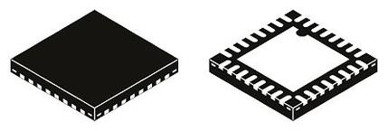
封装:
QFN-32
描述:
NXP SGTL5000XNAA3 音频编解码器, 耳机, 立体声, 1, 1, -40 °C, 85 °C, 96 kSPS
Pictures:
3D模型
符号图
焊盘图
引脚图
产品图
页面导航:
引脚图在P3P4Hot
典型应用电路图在P13P15P59P60
原理图在P2P12P20P23P59P60
封装尺寸在P61P62P63P64P65P66
型号编码规则在P1
封装信息在P61P62P63P64P65P66
功能描述在P3P12P13P14P15P16
技术参数、封装参数在P1P9
应用领域在P13P15P59P60
电气规格在P5P6P7P8P9P10P11P13
导航目录
SGTL5000XNAA3数据手册
Page:
of 68 Go
若手册格式错乱,请下载阅览PDF原文件
Analog Integrated Circuit Device Data
12 Freescale Semiconductor
SGTL5000
FUNCTIONAL DESCRIPTION
INTRODUCTION
FUNCTIONAL DESCRIPTION
INTRODUCTION
The SGTL5000 is a low power stereo codec with
integrated headphone amplifier. It is designed to provide a
complete audio solution for portable products needing
LINEIN, mic-in, LINEOUT, headphone-out, and digital I/O.
Deriving it’s architecture from best in class Freescale
integrated products that are currently on the market, the
SGTL5000 is able to achieve ultra low power with very high
performance and functionality, all in one of the smallest
footprints available. Target markets include portable media
players, GPS units and smart phones. Features such as
capless headphone design and USB clocking mode (12
MHz
SYS_MCLK input) help lower overall system cost.
In summary, the SGTL5000 accepts the following inputs:
• Line input
• Microphone input, with mic bias
• Digital I
2
S input
In addition, the SGTL5000 supports the following outputs:
• Line output
• Headphone output
• Digital I
2
S output
The following digital audio processing is included to allow
for product differentiation:
• Digital mixer
• Freescale Surround
• Freescale Bass Enhancement
• Tone Control, parametric equalizer, or graphic equalizer
The SGTL5000 can accept an external standard master
clock at a multiple of the sampling frequency (i.e. 256*Fs,
385*Fs, 512*Fs). In addition it can take non-standard
frequencies and use the internal PLL to derive the audio
clocks. The device supports 8.0
kHz, 11.025 kHz, 12 kHz,
16 kHz, 22.05 kHz, 24 kHz, 32 kHz, 44.1kHz, 48 kHz, 96 kHz
sampling frequencies.
FUNCTIONAL INTERNAL BLOCK DESCRIPTION
SYSTEM BLOCK DIAGRAM W/ SIGNAL FLOW AND
GAIN MAP
Figure 8 shows a block diagram that highlights the signal
flow and gain map for the SGTL5000.
To guarantee against clipping, it is important that the gain
in a signal path in addition to the signal level does not exceed
0 dB at any point.
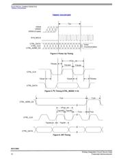
Figure 8. System Block Diagram, Signal Flow and Gain
MIC GAIN
(0dB, 20dB,
30dB, 40dB)
MIC_IN
Audio
Switch
I2S_DIN
ADC
I2S_DOUT
Mix
+6dB
Tone Control /GEQ/PEQ
+12 dB
Bass Enhancement
+6dB
Surround
AVC
+12dB
DAC
DAC Volume
Control
-90dB to 0dB
Headphone Volume Control
-52dB to +12dB
(CHIP_ANA_HP_CTRL)
HP_OUT
Analog Gain Digital Gain
Analog
Gain
(0 to
22.5dB)
Only Gain is shown for the Digital Audio Processing blocks. For complete description
please see Digital Audio Processing section.
Line Out Volume Control
(CHIP_LINE_OUT_VOL)
LINEOUT
LINE_IN
器件 Datasheet 文档搜索
AiEMA 数据库涵盖高达 72,405,303 个元件的数据手册,每天更新 5,000 多个 PDF 文件
