Datasheet 搜索 > 稳压芯片 > ADI(亚德诺) > ADP7156ACPZ-3.3-R7 数据手册 > ADP7156ACPZ-3.3-R7 产品设计参考手册 4/8 页
 器件3D模型
¥ 37.511
ADP7156ACPZ-3.3-R7 产品设计参考手册 - ADI(亚德诺)
制造商:
ADI(亚德诺)
分类:
稳压芯片
封装:
LFCSP-10
描述:
低压差稳压器 3.3/5Vin 1.2A Ultra Low Noise LDO, Fixed
Pictures:
3D模型
符号图
焊盘图
引脚图
产品图
页面导航:
原理图在P3
型号编码规则在P8
导航目录
ADP7156ACPZ-3.3-R7数据手册
Page:
of 8 Go
若手册格式错乱,请下载阅览PDF原文件

UG-809 EVAL-ADP7156 User Guide
Rev. 0 | Page 4 of 8
OUTPUT VOLTAGE MEASUREMENTS
3.29999
+ –
VOLTMETER
+ –
VOLTAGE
SOURCE
LOAD
12948-004
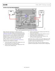
Figure 3. Output Voltage Measurement Setup for the ADP7156CP-3.3EVALZ
Figure 3 shows the connections to a voltage source and a
voltmeter for basic output voltage accuracy measurements for the
ADP7156CP-3.3EVALZ. Use a resistor as the load for the regulator.
Ensure the resistor has a power rating that can handle the power
dissipated across it. An electronic load can also be used as an
alternative to using a resistor load. Ensure the voltage source
supplies enough current for the expected load levels.
The steps on how to connect the ADP7156CP-3.3EVALZ to a
voltage source and a voltmeter are as follows:
1. Connect the negative terminal of the voltage source to one
of the GND pins on the evaluation board.
2. Connect the positive terminal of the voltage source to the
VIN pin on the evaluation board.
3. Connect a load between the evaluation board VOUT pin
and one of the GND pins.
4. Connect the negative terminal of the voltmeter to one of
the GND pins on the evaluation board.
5. Connect the positive terminal of the voltmeter to the
VOUT pin on the evaluation board.
When these steps are complete, turn on the voltage source. If the
JP1 jumper is inserted (connecting the EN pin to the VIN pin for
automatic startup), the regulator powers up.
If the load current is large, connect the voltmeter as close as
possible to the output capacitor to reduce the effects of voltage drops.
器件 Datasheet 文档搜索
AiEMA 数据库涵盖高达 72,405,303 个元件的数据手册,每天更新 5,000 多个 PDF 文件
