Datasheet 搜索 > 编解码器 > ADI(亚德诺) > AD1938WBSTZ 数据手册 > AD1938WBSTZ 产品设计参考手册 6/32 页
 器件3D模型
¥ 22.788
AD1938WBSTZ 产品设计参考手册 - ADI(亚德诺)
制造商:
ADI(亚德诺)
分类:
编解码器
封装:
LQFP-48
描述:
ANALOG DEVICES AD1938WBSTZ 音频编解码器, AEC-Q100, 立体声, 4, 8, -40 °C, 105 °C, 192 kSPS
Pictures:
3D模型
符号图
焊盘图
引脚图
产品图
页面导航:
原理图在P9P10P11P12P13P14P15P16P17
型号编码规则在P26

导航目录
AD1938WBSTZ数据手册
Page:
of 32 Go
若手册格式错乱,请下载阅览PDF原文件

UG-045 Evaluation Board User Guide
Rev. 0 | Page 6 of 32
In this mode, the AD1938 ADC port generates BCLK and
LRCLK when given a valid MCLK.
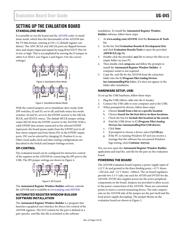
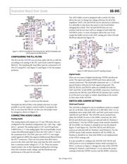
For full flexibility of the AD1938, the part can be put in SPI
control mode and programmed with the Automated Register
Window Builder application (see Figure 4 for the appropriate
jumper settings). Changing the registers and setting the DIP
switches allow many possible configurations. In the various
master and slave modes, the AD1938 takes MCLK from a
selected source and can be set to generate or receive either
BCLK or LRCLK to or from either the ADC or the DAC port,
depending on the settings and requirements.
As an example, to set the ADC port as master, switch the ADC
Control 2 register bits for BCLK and LRCLK to master, and
change S2, Position 2 and Position 5, to on. In this mode, the
board is configured so that the ADC BCLK and LRCLK pins are
the clock source for both the ADC destination and the DAC
data source. For the DAC port to be the master, the DAC
Control 1 register bits for BCLK and LRCLK must be changed
to master, and S2, Position 2 and Position 3, and S2, Position 5
and Position 6, must all be on. On this evaluation board, these
settings allow the master port on the AD1938 to drive both the
S/PDIF and the HDR connections. Many combinations of master
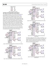
and slave are possible (see Figure 15 and Figure 16 for the correct
settings).
S/PDIF Audio
The settings shown in Figure 15 and Figure 16 show the details
of clock routing and control for both the ADC and DAC ports.
The board is shipped with the S/PDIF port selected as the
default; the hex switches are set to 0, and all DIP switches are
set to off. The AD1938 is shipped in standalone mode (see
Figure 2); the BCLK and LRCLK signals run from the S/PDIF
receiver to the ADC and DAC ports of the AD1938.
In this default configuration, the DAC audio path routes the
S/PDIF audio signal to all four stereo AD1938 DSDATA inputs
simultaneously. The rotary switch, S4, allows the user to select
individual stereo pairs for transmission of the analog signal.
Position 0 is the default; Position 1 through Position 4 allow the
S/PDIF input signal to be assigned to Pair 1 to Pair 4, respectively.
Also in this default configuration, the IN1 analog is routed through
the AD1938 ADC ASDATA1 path to the S/PDIF output. IN2 is
selected by changing the S3 DIP switch, Position 8, from 0 to 1.
HDR Connectors—Serial Audio
Routing of serial audio to and from the HDR1 connector is con-
trolled by DIP S3, Position 6 and Position 7, and Rotary S4. For
the DAC audio signal path, S4, Position 8, assigns the data
signal coming into HDR1 DSDATA1 to all four DSDATA ports
on the AD1938. S4, Position 9, assigns the HDR1 labeled ports
to the associated port on the AD1938.
Other Options
It is possible to mute all data going to the DSDATA ports of the
AD1938 by selecting S4, Position 7. This shows the SNR of the
DACs
To use other f
S
rates, the USBi must be connected and the
AD1938 registers must be programmed accordingly. For
example, adjusting the f
S
rate to 96 kHz requires that the ADC
and DAC Control 0 registers have sample rates set to 96 kHz
(see Figure 15 and Figure 16 for the complete list of options).
The CPLD code is presented in the CPLD Code section and is
included with the evaluation board; alterations and additions to
the functionality of the CPLD are possible by altering the code
and reprogramming the CPLD.
器件 Datasheet 文档搜索
AiEMA 数据库涵盖高达 72,405,303 个元件的数据手册,每天更新 5,000 多个 PDF 文件
